VFDDistributor

Air compressor application selection

VFDs for Air Compressors

Selecting a VFD for an air compressor starts with positive-displacement constant-torque physics, not a generic horsepower or fan-and-pump kW label. Oil-injected rotary screw, oil-free dry screw and reciprocating piston compressors trap a fixed volume of air per shaft revolution against plant receiver backpressure, demanding 100% rated shaft torque from minimum speed to base speed plus 150%–180% breakaway current during loaded restarts. Before comparing drive catalog codes, verify Heavy-Duty (HD / High Overload 150% for 60s) continuous current margin including motor Service Factor, 4–20 mA closed-loop PID pressure regulation within a ±1.5 PSI (±0.1 bar) band, sleep/wake sump blowdown interlocks and the 20–25 Hz minimum speed floor required for airend oil-film sealing and TEFC motor cooling. Send your compressor and motor nameplate data on WhatsApp for a multi-brand VFD or retrofit panel sourcing check.

  • Heavy-Duty 150% constant-torque current sizing verified against motor Service Factor
  • 4–20 mA PID header pressure regulation (±1.5 PSI), sleep/wake and blowdown interlocks
  • 20–25 Hz minimum oil-lubrication floor, PTC/PT100 protection and multi-brand sourcing via WhatsApp
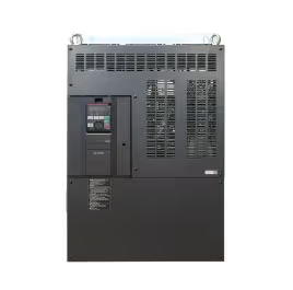
Heavy-duty industrial variable frequency drive configured for rotary screw air compressor speed and pressure control

Selection foundation

Size for positive-displacement constant torque, not a fan-and-pump kW table.

While the main Variable Frequency Drives category covers general industrial motor control, this engineering and sourcing page addresses the electrical, thermodynamic and mechanical boundaries unique to industrial air compressors. Unlike centrifugal fans and water pumps—where torque drops with the square of speed—rotary screw and reciprocating air compressors require full rated current at low speed, open-loop sensorless vector or permanent-magnet vector torque control, strict minimum frequency clamps to protect oil circulation, and input harmonic mitigation on high-kilowatt plant feeders. Once your motor full-load current, Service Factor, supply voltage, compressor mechanism and pressure-transducer loop are defined, our team matches current-production VFD catalog numbers or enclosed compressor retrofit panels across major drive manufacturers. Mentioning OEM series names on this page defines technical selection paths; exact part numbers, firmware options and regional lead times are confirmed per quotation.

01

Heavy-Duty (150% / 60s) current sizing

Positive-displacement compressors require Constant-Torque Heavy-Duty (I_HD / High Overload) ratings. Size I_HD above motor nameplate FLA multiplied by the NEMA 1.15 Service Factor and 45°C–50°C canopy ambient derating—which typically steps the VFD up one full frame size over a Normal-Duty fan/pump label.

02

4–20 mA PID & sleep/wake hysteresis

Hold plant header pressure within ±1.5 PSI (±0.1 bar) using a shielded 24 VDC loop-powered 4–20 mA receiver transducer with < 3.5 mA wire-break fault detection, reverse-acting PID tuning, sleep entry delay timers and a 15–30 second sump blowdown interlock before restart.

03

20–25 Hz minimum lubrication floor

Hard-clamp minimum output frequency (f_min = 20–25 Hz on oil-flooded screw units; 25–30 Hz on splash-lubricated piston units) so separator differential pressure, oil-film lobe sealing, cooling oil flow andairend discharge temperature (< 105°C) never collapse at low speed.

04

Motor cooling, dV/dt & IEEE 519 harmonics

Running 100% constant torque at 20–25 Hz reduces TEFC (IC411) shaft-fan cooling while stator I²R heating stays at 100%. Verify NEMA MG 1 Part 31 insulation, PTC/PT100 thermistor trips, IC416 forced blowers where required, and 3%–5% AC line reactors or DC link chokes.

How air compressor VFDs are engineered

Match Heavy-Duty current, PID pressure control and minimum speed to the compressor airend

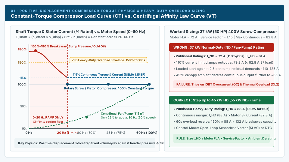
Engineering chart comparing constant-torque positive-displacement compressor load curves against centrifugal variable-torque curves and 37 kW Heavy-Duty VFD sizing
Positive-displacement screw and piston compressors demand 100%–115% constant torque across 20–60 Hz and 150%–180% breakaway torque. Always select the VFD frame from the 150%/60s Heavy-Duty (I_HD) current table.

01 · Duty & torque physics

Why rotary screw and reciprocating compressors require Heavy-Duty Constant-Torque (150%) VFD sizing

In a centrifugal fan or centrifugal water pump, fluid pressure rises with the square of impeller tip speed (H ∝ n²), so resistive shaft torque follows a quadratic variable-torque curve (T ∝ n²) and shaft power follows the cube of speed (P ∝ n³). At 50% speed (30 Hz), a centrifugal fan demands only 25% torque and 12.5% power. An oil-injected rotary screw, oil-free screw, reciprocating piston, rotary vane or scroll air compressor is fundamentally different: it is a positive-displacement (PD) machine. Every revolution of the male and female screw rotors—or every stroke of the crankshaft—traps a fixed geometric displacement volume (V_disp, in liters/rev or in³/rev) and compresses that gas parcel against the downstream oil separator and plant air receiver backpressure (typically 100 to 175 PSIG / 7.0 to 12.0 bar).

Because plant header discharge pressure (p_discharge) is maintained at setpoint regardless of whether the drive commands 1,200 RPM (20 Hz) or 3,600 RPM (60 Hz), the resistive torque required per shaft revolution remains constant across the entire operating speed range: T_shaft = (p_effect × V_disp) / (2π × η_mech) ≈ Constant (100% rated torque from 20 Hz to 60 Hz). Volumetric air delivery scales linearly with speed (Q_air ∝ n), and compressor shaft power scales linearly with speed: P_shaft (kW) = (T_shaft × n) / 9550 ∝ n. Consequently, motor stator current stays at 100% of full-load amps (FLA) even when the compressor slows to 20 Hz.

Industrial drive manufacturers (including ABB ACS580/ACS880, Yaskawa GA800/A1000, Siemens SINAMICS G120/S120 and Allen-Bradley PowerFlex 753/755) publish dual ratings on each hardware frame: Normal Duty (ND / Light Duty I_Ld / Low Overload LO at 110% overload for 60 seconds) for fans and pumps, and Heavy Duty (HD / Constant Torque I_Hd / High Overload HO at 150% overload for 60 seconds and 180%–200% for 2–3 seconds) for constant-torque machinery. When an oil-injected screw compressor starts before the separator blowdown valve has completely vented residual pressure, or accelerates cold ISO VG 46/68 synthetic lubricant against 110 PSIG backpressure, breakaway torque spikes to 140%–180% of rated torque. On a nominal 37 kW (50 HP) 400V screw compressor with a 72 A motor FLA and a continuous NEMA 1.15 Service Factor (72 A × 1.15 = 82.8 A continuous current), selecting a "37 kW Normal Duty" VFD (I_ND = 72 A, I_HD = 61 A, current limit clamped at 79.2 A) causes immediate IGBT Overcurrent (OC) or Drive Thermal Overload (OL2) trips. You must size from the Heavy-Duty table so I_HD ≥ Motor FLA × Service Factor × Canopy Ambient Derating—stepping up to a 45 kW HD (55 kW ND, I_HD = 88 A) frame and commissioning Open-Loop Sensorless Vector (SLVC), Direct Torque Control (DTC) or Encoderless PM Vector control rather than quadratic V/f mode.

Constant torque across 20–60 Hz
Each rotor revolution compresses a fixed volume against header backpressure; torque and stator current remain at 100% down to minimum speed.
150%–180% breakaway reserve
Heavy-Duty (150% for 60s, 180%–200% peak) overload capacity absorbs residual sump pressure, cold oil viscosity and piston TDC compression peaks.
NEMA 1.15 Service Factor & 45°C canopy derating
Size I_HD ≥ FLA × 1.15 SF and apply 1.5%–2.5%/°C temperature derating when the VFD is mounted inside a 45°C–50°C acoustic compressor enclosure.
Sensorless Vector, DTC or PM-SLVC mode
Never use fan/pump quadratic V/f² mode. Configure Open-Loop Sensorless Vector or DTC for induction motors, or high-frequency standstill angle ID for iPM synchronous motors.
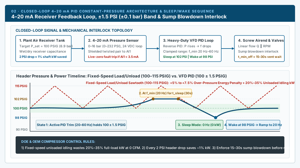
Schematic of 4-20 mA closed-loop PID air receiver pressure regulation within ±1.5 PSI and sleep/wake hysteresis timeline compared with 100-115 PSIG load/unload cycling
Closed-loop 4–20 mA PID control eliminates both the 10–15 PSI over-pressurization band (1% power per 2 PSI) and the 20%–35% unloaded idling kW loss, while t_min_off protects the drive from loaded restarts against trapped sump pressure.

02 · Closed-loop 4–20 mA PID & sleep/wake control

Eliminating the 10–15 PSI load/unload band and 20%–35% unloaded idling power penalty

Fixed-speed rotary screw compressors regulate plant air capacity through either inlet butterfly valve modulation or load/unload pressure-switch cycling. Per the U.S. Department of Energy (DOE) Uniform Methods Project Chapter 22 Compressed Air Evaluation Protocol and the DOE Compressed Air Sourcebook, throttling an intake butterfly valve increases the internal compression ratio across the airend, consuming ~80%–85% of full-load kW at 50% air flow and ~70% of full-load kW at 0% flow. Load/unload control closes the inlet valve and vents the separator tank when header pressure reaches the unload cutout (for example, 115 PSIG / 8.0 bar), but leaves the main induction motor spinning at 1,800 or 3,600 RPM—burning 20% to 35% of full-load electrical power while delivering zero cubic feet per minute (0 CFM).

In addition, because across-the-line or star-delta starters restrict large compressor motors to 2–4 starts per hour to prevent stator thermal breakdown, a fixed-speed load/unload machine requires a wide 10 to 15 PSI (0.7 to 1.0 bar) deadband above the minimum plant operating pressure (for example, loading at 100 PSIG and unloading at 115 PSIG). Because every 2 PSI (0.14 bar) increase in discharge pressure increases shaft power consumption by approximately 1% and drives ~1.4% higher artificial air leakage across unregulated pneumatic tools and pipe fittings, operating in a 100–115 PSIG sawtooth band wastes 4% to 7% in over-pressurization energy alone.

A VFD-controlled trim compressor replaces that 15 PSI sawtooth with a closed-loop 4–20 mA PID regulator that holds receiver header pressure within ±1.5 PSI (±0.1 bar) of the target setpoint (such as 100 PSIG / 6.9 bar). Wire a 2-wire loop-powered 4–20 mA pressure transducer (0–10 bar or 0–16 bar range, excited by the VFD internal 24 VDC supply) on the wet or dry air receiver to the drive analog input AI1 using twisted-pair shielded instrumentation cable grounded 360 degrees at the panel entry. Always select 4–20 mA current feedback over 0–10 V voltage feedback: current loops reject IGBT PWM electromagnetic interference and provide a 4 mA live zero. Programming the drive Analog Input Loss fault (< 3.5 mA) to execute a controlled stop or safe fallback speed prevents a severed sensor cable from reading 0 PSI and running the compressor to 100% speed against the safety relief valve. When air demand drops below the 20–25 Hz minimum speed floor and pressure rises to P_sleep (102 PSIG) for the sleep delay timer (t_sleep = 20–60 s), the drive closes the inlet valve, vents the sump, decelerates to 0 Hz (0 kW), enforces a mandatory 15–30 second minimum-off blowdown timer (t_min_off) so internal sump pressure vents below 1.0–1.5 bar, and wakes immediately when header pressure touches P_wake (98 PSIG).

2 PSI = 1% shaft power rule
Replacing a 100–115 PSIG load/unload sawtooth with a 100 ± 1.5 PSIG VFD PID band lowers average discharge pressure by 8–12 PSI, cutting compression energy by 4%–6% plus artificial leak demand.
4–20 mA live-zero wire-break protection
Configure AI1 < 3.5 mA fault detection so a broken transducer wire triggers a safe stop or fallback speed instead of interpreting 0 mA as 0 PSI and over-pressurizing the receiver.
Reverse PID tuning for receiver capacitance
Set Reverse (negative feedback) PID action with moderate proportional gain (Kp = 1.5–4.0), integral time matched to receiver volume (Ti = 5–15 s) and zero derivative gain (Td = 0 s).
4-stage Sleep / Wake & blowdown interlock
Require f = f_min and P ≥ P_sleep for 20–60s before sleeping, and enforce a 15–30s minimum-off timer (t_min_off) so separator pressure vents below 1.5 bar before wake-up.
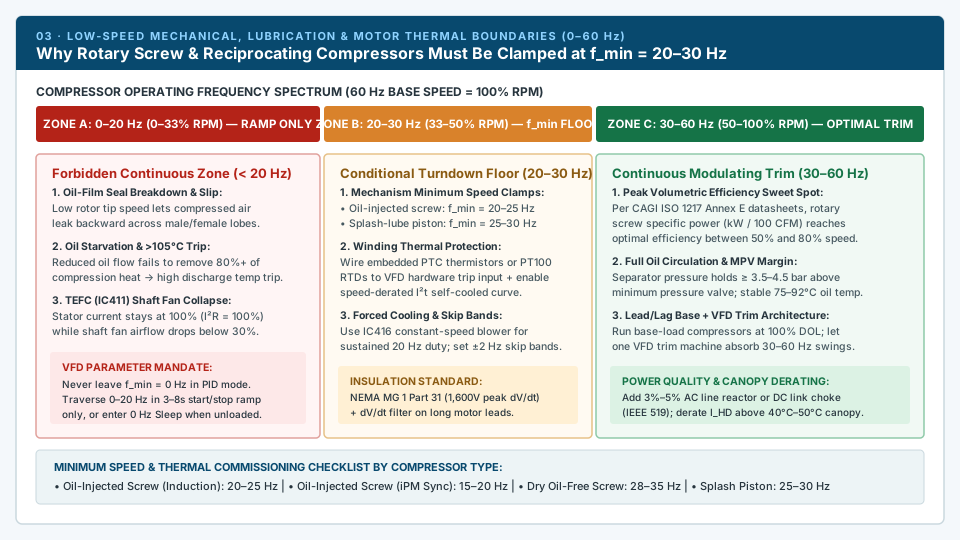
Three-zone frequency map from 0 to 60 Hz illustrating rotary screw oil lubrication starvation below 20 Hz, conditional constant-torque floor at 20-30 Hz, and optimal modulating trim at 30-60 Hz
Hard-clamp VFD minimum frequency at 20–25 Hz (screw) or 25–30 Hz (splash piston) during loaded PID operation, and protect TEFC stator windings with PTC/PT100 hardware trips and speed-derated I²t thermal curves.

03 · Minimum speed (20–25 Hz), lubrication & thermal limits

Protecting rotary screw oil circulation, volumetric efficiency and TEFC motor windings at low RPM

A variable frequency drive can electrically spin an AC motor at 3 Hz, but running a standard air compressor below its mechanical minimum speed floor (f_min = 20–25 Hz on oil-injected rotary screw units, 28–35 Hz on dry oil-free screw units, and 25–30 Hz on splash-lubricated reciprocating piston units) rapidly destroys the airend or overheats the motor. In an oil-injected rotary screw airend, the male and female rotors do not make metal-to-metal contact; a hydrodynamic film of injected lubricant seals the clearance gap between the rotor lobes and housing while absorbing more than 80% of the heat of compression. Below 35%–40% of rated speed (< 20–25 Hz on a 60 Hz motor), rotor tip speed drops below the sealing threshold: hot compressed air slips backward from the discharge port to the suction port, volumetric efficiency collapses, and specific package input power (kW per 100 CFM verified on CAGI ISO 1217 Annex E datasheets) spikes upward.

Simultaneously, most oil-flooded rotary screw compressors do not use a separate positive-displacement gear oil pump; they rely on air-oil separator tank pressure maintained by the Minimum Pressure Valve (MPV, typically 50–65 PSIG / 3.5–4.5 bar) to force oil through the cooler, filter, rotor bearings and compression chamber. Operating below 20 Hz starves oil circulation while hot internal back-leakage compounds thermal load, driving airend discharge temperature past the 105°C–110°C (221°F–230°F) high-temperature shutdown trip. On splash-lubricated reciprocating piston compressors, connecting-rod dippers require at least 25–30 Hz (50% speed) to sling crankcase oil onto cylinder walls and wrist pins, and low-speed operation must avoid torsional resonance frequencies via 1–3 programmable VFD skip-frequency bands (±2 Hz).

Low-speed constant-torque operation also creates a severe motor thermal bottleneck. On a standard Totally Enclosed Fan-Cooled (TEFC / IEC IC411) induction motor, the cooling fan is mounted directly on the motor shaft. At 20 Hz (33% speed), cooling airflow over the stator frame drops to roughly one-third, yet stator current (I) and copper resistive heating (P_Cu = 3 × I² × R_s) remain at 100%—augmented by 5%–10% additional PWM harmonic switching losses. To prevent stator insulation failure, verify three protections before commissioning: (1) hard-clamp VFD minimum frequency (such as ABB Par 30.11, Yaskawa d2-02, Siemens p1080) to the compressor OEM floor (20–30 Hz); (2) wire embedded motor PTC thermistors or PT100 RTD sensors directly to the VFD hardware thermistor trip input and set the electronic overload (I²t) curve to Self-Cooled / Speed-Dependent Constant Torque (or install an IC416 constant-speed forced cooling blower for continuous 20 Hz duty); and (3) confirm NEMA MG 1 Part 31 inverter-duty insulation (1,600V peak dV/dt withstand) plus a 3%–5% AC line reactor or DC link choke to control IEEE 519 input current harmonics.

Hard-clamp f_min (never 0 Hz in PID)
Set minimum output frequency to 20–25 Hz on oil-injected screw, 15–20 Hz on iPM screw, 28–35 Hz on oil-free dry screw, and 25–30 Hz on splash-lubricated piston compressors.
Airend oil-film seal & 105°C trip prevention
Maintaining speed above f_min preserves separator differential pressure (≥ 3.5 bar across the MPV) and oil flow needed to carry away 80%+ of compression heat.
TEFC (IC411) vs. Forced Blower (IC416)
At 20 Hz, a shaft-driven fan loses two-thirds of its cooling airflow while stator I²R heating stays at 100%. Use speed-derated I²t + PTC/PT100 trips, or specify an IC416 blower.
NEMA MG 1 Part 31 & IEEE 519 reactors
Confirm 1,600V peak phase-to-phase insulation, add output dV/dt filters on long compressor room motor leads, and include 3%–5% AC line reactors or DC chokes on large kW feeders.

Compressor duties

Air compressor mechanisms that govern VFD selection

Oil-injected rotary screw, interior permanent magnet (iPM) screw, oil-free dry screw and reciprocating piston compressors impose distinct starting torque peaks, minimum lubrication speeds and motor control algorithms.

Browse VFD model reference library
01

Oil-injected rotary screw (Induction motor, 7.5–250 kW)

Requires 100% constant torque across 20–60 Hz and 150%–180% breakaway current if restarted against residual sump pressure. Size from the VFD Heavy-Duty (I_HD, 150%/60s) table covering the motor 1.15 Service Factor, commission Open-Loop Sensorless Vector or DTC, clamp f_min at 20–25 Hz, and wire a 4–20 mA receiver transducer for ±1.5 PSI PID trim.

Typical fit: Primary plant trim air compressors, OEM screw packages and cabinet VFD retrofits

02

Permanent-magnet synchronous rotary screw (iPM, 7.5–160 kW)

Compact IE4/IE5 interior permanent magnet (iPM) synchronous compressor motors eliminate rotor slip losses and allow wider turndown (15–20 Hz), but cannot run on a standard induction-only VFD. Confirm the exact drive catalog code supports encoderless PM vector control (PM-SLVC), standstill high-frequency rotor-pole angle identification (preventing reverse rotation on start) and back-EMF constant (Ke) tuning.

Typical fit: High-efficiency integrated VSD+ screw packages and replacement PM compressor drives

03

Oil-free dry screw & tooth compressors (37–315 kW)

Two-stage dry screw rotors operate with tight mechanical clearances and zero oil film to seal internal slip or absorb compression heat. Minimum speed must be clamped higher (f_min = 28–35 Hz / 50%–60% speed) to prevent rapid interstage and discharge overheating, paired with fast vector current limiting and water-jacket or IC416 forced motor cooling.

Typical fit: Food, pharmaceutical, electronics and instrument-air oil-free compressor stations

04

Reciprocating piston compressors (2.2–160 kW)

Compression strokes through top-dead-center generate severe cyclic torque pulsations (160%–200% peak). Always open an automated unloader solenoid valve during start/stop ramps, oversize VFD Heavy-Duty current by 20%–30% to absorb current pulsations, clamp f_min at 25–30 Hz for splash-lubricated crankcases (20–25 Hz with shaft oil-pump pressure interlock), and program skip-frequency bands around frame resonance.

Typical fit: High-pressure industrial shop air, PET bottling boosters and process gas piston units

Engineering specification matrix

Air Compressor VFD Sizing, Minimum Speed & Control Matrix by Mechanism

Use this six-column engineering matrix to verify torque class, Heavy-Duty overload current margin, minimum speed floor (f_min), closed-loop PID sleep/wake parameters and motor protection before requesting a model match.

Oil-Injected Rotary Screw (Induction Motor, 7.5–250 kW)

Torque & Breakaway Profile
100% Constant Torque across full speed range; 150%–180% breakaway if started before full sump blowdown
Required VFD Duty Class & Control Mode
Heavy Duty (HD / I_Hd): 150% overload for 60s; Open-Loop Sensorless Vector (SLVC) or DTC
Minimum Speed Floor (f_min) & Limiting Physics
20–25 Hz (35%–40% speed): Oil-film lobe sealing, separator differential oil circulation (≥ 3.5 bar), and 105°C airend temp trip
Closed-Loop PID & Sleep/Wake Strategy
4–20 mA receiver transducer (±1.5 PSI band); Sleep after 20–60s at f_min; 15–30s blowdown wait before restart
Critical Motor & Power-Quality Checks
Size I_HD ≥ Motor FLA × 1.15 SF; NEMA MG 1 Part 31 insulation; PTC thermistor trip; 3%–5% AC reactor or DC choke

Oil-Injected Rotary Screw (PM Synchronous iPM Motor, 7.5–160 kW)

Torque & Breakaway Profile
100% Constant Torque from 15% to 100% speed; high starting torque without rotor slip
Required VFD Duty Class & Control Mode
Heavy Duty (HD 150% / 60s) with Encoderless PM Vector Control (PM-SLVC) and high-frequency standstill angle ID
Minimum Speed Floor (f_min) & Limiting Physics
15–20 Hz (wider turndown): Limited by airend internal back-leakage and oil flow rather than rotor slip heating
Closed-Loop PID & Sleep/Wake Strategy
Fast PID pressure tracking (±0.1 bar); enter Sleep when demand drops below minimum volumetric efficiency floor
Critical Motor & Power-Quality Checks
Confirm VFD firmware supports interior PM (IPM) back-EMF constant (Ke), pole count, and anti-rollback startup

Oil-Free Dry Screw / Tooth Compressor (Two-Stage, 37–315 kW)

Torque & Breakaway Profile
100% Constant Torque; tight dry-rotor clearances with zero oil sealing margin
Required VFD Duty Class & Control Mode
Heavy Duty (HD 150% / 60s); fast current-limiting vector control
Minimum Speed Floor (f_min) & Limiting Physics
28–35 Hz (50%–60% speed): Without injected oil to seal lobes or absorb heat, low tip speed causes rapid interstage/discharge overheating
Closed-Loop PID & Sleep/Wake Strategy
Narrow PID trim band (4–20 mA); transition to unloaded purge or Sleep immediately at f_min
Critical Motor & Power-Quality Checks
Water-jacket or IC416 forced-air motor cooling; check interstage pressure & temperature interlocks

Reciprocating Piston Compressor (Splash-Lubricated, 2.2–37 kW)

Torque & Breakaway Profile
Pulsating Constant Torque (160%–200% peak torque pulses per crankshaft stroke through TDC)
Required VFD Duty Class & Control Mode
Heavy Duty (HD 150% / 60s, 180%–200% / 3s); Sensorless Vector with high inertia/current limit margin
Minimum Speed Floor (f_min) & Limiting Physics
25–30 Hz (50% speed): Connecting-rod splash dippers lose crankcase oil throw below 50% RPM; flywheel pulsation rises at low speed
Closed-Loop PID & Sleep/Wake Strategy
Pressure switch or 4–20 mA PID with mandatory unloader solenoid valve open during start and stop ramps
Critical Motor & Power-Quality Checks
Oversize VFD Heavy-Duty current by 20%–30% to absorb cyclic current peaks; verify mechanical resonance skip frequencies

Reciprocating Piston Compressor (Pressure-Lubricated Industrial, 30–160 kW)

Torque & Breakaway Profile
Pulsating Constant Torque; high breakaway inertia from heavy flywheel
Required VFD Duty Class & Control Mode
Heavy Duty (HD 150% / 60s); Vector control + crank-angle peak current damping
Minimum Speed Floor (f_min) & Limiting Physics
20–25 Hz (40%–50% speed): Shaft-driven oil pump pressure switch (≥ 1.5–2.0 bar) + torsional vibration critical speeds
Closed-Loop PID & Sleep/Wake Strategy
Multi-step loader + VFD trim between steps; program 1–3 Skip Frequency Bands (±2 Hz) around frame resonance
Critical Motor & Power-Quality Checks
Verify oil-pressure low-trip digital input interlock (DI) and IC416 blower or speed-derated I²t protection

Centrifugal / Turbo Air Compressor (Dynamic Impeller)

Torque & Breakaway Profile
Variable Torque (T ∝ n²) above surge line
Required VFD Duty Class & Control Mode
Dynamic high-speed OEM package or Medium-Voltage drive with active Surge Control
Minimum Speed Floor (f_min) & Limiting Physics
Bounded by Surge Limit Line (~65%–75% speed): Dropping speed below surge causes violent reverse-flow aerodynamic stall
Closed-Loop PID & Sleep/Wake Strategy
Coupled pressure + inlet guide vane (IGV) + anti-surge blow-off control (not a single-loop 4–20 mA PID)
Critical Motor & Power-Quality Checks
Do not apply general-purpose pump PID macros; requires anti-surge controller and high-speed bearing protection

Quick selection

Send your air compressor and motor data.

Select your compressor mechanism, motor power and supply voltage. WhatsApp opens with this page reference (APP-VFD-COMPRESSORS) attached; add motor nameplate amps (FLA + Service Factor), target discharge pressure (PSI/bar) and existing drive code if replacing.

Typical specification scope

What we can match

Required overload duty
Heavy Duty (HD / High Overload I_Hd): 150% rated current for 60s, 180%–200% breakaway for 2–3s
Current sizing formula
I_HD ≥ Motor Nameplate FLA × Service Factor (1.15) × Canopy Ambient Derating (45°C–50°C)
Motor control modes
Open-Loop Sensorless Vector (SLVC), Direct Torque Control (DTC), or Encoderless PM Vector (iPM)
Minimum frequency floor
20–25 Hz (oil-injected screw), 15–20 Hz (iPM screw), 28–35 Hz (oil-free screw), 25–30 Hz (splash piston)
Pressure feedback & PID
4–20 mA loop-powered transducer (24 VDC, < 3.5 mA wire-break fault), ±1.5 PSI (±0.1 bar) deadband
Sleep / wake interlocks
Sleep delay 20–60s at f_min; mandatory 15–30s minimum-off sump blowdown timer before restart
Motor & harmonic protection
NEMA MG 1 Part 31 insulation, PTC/PT100 thermistor input, 3%–5% AC line reactor or DC link choke
Supply scope
Standalone Heavy-Duty VFD, OEM replacement unit, or enclosed compressor VFD retrofit panel

Application checks

Limits that change the commercial next step

Base-load 100% duty vs. variable-demand trim duty

Per U.S. DOE guidance, if a plant air compressor runs continuously at 95%–100% capacity 24 hours a day, adding a VFD introduces 2%–3% inverter switching losses without saving energy. In multi-compressor rooms, run base-load machines at 100% full-load efficiency across the line (or via soft starters) and assign one VFD-controlled rotary screw compressor sized to span the trim capacity gap between base units.

Internal canopy replacement vs. external wall/floor VFD panel

Mounting a replacement VFD inside an existing acoustic compressor canopy exposes the drive to 45°C–50°C ambient heat, oil mist and tight footprint constraints. External wall-mounted or floor-standing VFD panels simplify cooling, house the 3%–5% line reactor and disconnect switch, and isolate the drive from compressor frame vibration.

Induction motor vs. Interior Permanent Magnet (iPM) screw replacement

Many late-model variable-speed rotary screw compressors use compact IE4/IE5 interior permanent magnet (iPM) motors without encoders. When replacing a failed proprietary OEM compressor drive, confirm the motor nameplate first: an iPM motor requires a VFD with high-frequency standstill angle identification and back-EMF tuning so the airend never kicks backward at startup.

Single-phase shop supply on 5–15 HP air compressors

Running a three-phase 230V compressor motor from a single-phase 230V shop service requires severe DC-bus ripple and input rectifier derating—typically stepping up 2 to 3 drive frame sizes and verifying that the motor can deliver 150% constant-torque starting current under single-phase input rules.

Decision guide

Choose a supply path before comparing catalog numbers

Heavy-Duty standalone VFD (IP20 / UL Open Type)

Choose when
Installing inside an existing ventilated compressor control cabinet or MCC section with clean cooling airflow.
Verify before ordering
Heavy-Duty continuous current (I_HD ≥ FLA × 1.15 SF at 45°C–50°C), physical mounting footprint, DC choke/reactor space and 4–20 mA / PTC terminal assignments.

Encoderless PM Vector VFD (iPM synchronous motor)

Choose when
The rotary screw compressor uses an IE4/IE5 permanent-magnet synchronous motor rather than a squirrel-cage induction motor.
Verify before ordering
Exact firmware support for interior PM (IPM) control, rated motor frequency (often 100–200 Hz), pole count, back-EMF voltage (Ke) and anti-rollback starting.

Enclosed compressor VFD retrofit panel (IP54 / NEMA 12)

Choose when
Retrofitting a fixed-speed rotary screw compressor where the internal starter box has no room or cooling for a VFD.
Verify before ordering
Main circuit breaker/fuses, 3%–5% AC line reactor, cabinet cooling fans/filters, 24 VDC 4–20 mA transducer terminal block, and interlocking with the compressor load/unload solenoid.

Power-quality & long-cable protection package

Choose when
The compressor is a large share of plant transformer kVA (IEEE 519) or motor leads exceed 15–30 meters.
Verify before ordering
3%–5% AC line reactor or passive harmonic filter on the supply side; dV/dt filter or output reactor to protect motor winding insulation from reflected-wave voltage spikes.

Heavy-duty soft starter (Fixed-speed base-load unit)

Choose when
The compressor runs at 100% full load continuously and only needs reduced starting current (300%–400% FLA) during unloaded startup.
Verify before ordering
Unloaded starting torque curve, starts per hour, internal/external bypass contactor and overload class (see our Soft Starters category).

From requirement to quotation

A direct path from compressor nameplate data to a verified VFD quote

1

Send compressor & motor nameplate data on WhatsApp

Opening WhatsApp from this page automatically attaches reference APP-VFD-COMPRESSORS. Include motor FLA, Service Factor, compressor type and supply voltage so our first engineering check is exact.

2

Verify Heavy-Duty amps, control mode & interlocks

We verify the 150% Heavy-Duty current rating after canopy temperature derating, confirm induction SLVC or iPM vector compatibility, and check 4–20 mA PID, PTC thermistor and blowdown relay I/O.

3

Receive a verified multi-brand VFD or panel quotation

You receive a clear quotation naming the exact manufacturer catalog code, frame size, reactor/filter accessories, lead time and delivery terms—with zero unverified drop-in assumptions.

Frequently asked questions

Practical answers before you request a quote

Can I size an air compressor VFD using the drive’s Normal-Duty (fan and pump) kW rating?

No. Positive-displacement rotary screw and reciprocating compressors are Constant-Torque (CT) loads that draw 100% rated motor current from 20 Hz to 60 Hz and require 150%–180% starting and re-acceleration current. Normal-Duty (110% overload for 60s) ratings are designed for centrifugal fans and pumps where current drops with the square of speed. Always size an air compressor VFD from the manufacturer’s Heavy-Duty (HD / High Overload 150% for 60s) continuous current table, including the motor’s 1.15 Service Factor and 45°C–50°C canopy ambient derating—which usually requires stepping up one full frame size.

What is the minimum frequency (Hz) a rotary screw air compressor can run on a VFD?

For standard oil-injected rotary screw compressors driven by induction motors, minimum output frequency (f_min) must be hard-clamped between 20 Hz and 25 Hz (35%–40% of 60 Hz base speed). Below 20–25 Hz, rotor tip speed is too low to maintain the hydrodynamic oil film that seals the clearance between the male and female lobes; compressed air slips backward, separator differential pressure drops below the 3.5–4.5 bar Minimum Pressure Valve threshold, oil circulation starves, and airend discharge temperature rapidly exceeds the 105°C–110°C high-temperature shutdown limit. Splash-lubricated reciprocating compressors require an even higher floor of 25–30 Hz (50% speed), while oil-free dry screw units typically require 28–35 Hz.

How should the 4–20 mA pressure transducer and PID sleep/wake loop be configured?

Install a 2-wire loop-powered 4–20 mA pressure transducer (typically 0–10 bar or 0–16 bar) on the air receiver tank downstream of the check valve and wire it with shielded twisted-pair cable to the VFD analog current input (AI1). Set PID action to Reverse (frequency decreases as pressure rises) to hold header pressure within ±1.5 PSI (±0.1 bar). Enable Analog Input Loss detection (< 3.5 mA) to trip or drop to a safe fallback speed if the sensor wire breaks. Configure Sleep mode so that when the drive stays at f_min (20–25 Hz) and pressure exceeds P_sleep (e.g., 102 PSIG) for 20–60 seconds, the inlet valve unloads, the sump vents, the drive decelerates to 0 Hz, and a mandatory 15–30 second minimum-off timer (t_min_off) elapses before waking at P_wake (e.g., 98 PSIG).

Will retrofitting a VFD onto a fixed-speed rotary screw compressor always save energy?

A VFD saves substantial energy (typically 15% to 35% per U.S. DOE evaluations) only when plant air demand fluctuates between 40% and 90% of capacity—eliminating the 20%–35% unloaded idling power penalty and lowering average header pressure by 8–12 PSI (at ~1% power saved per 2 PSI reduction). However, if a base-load compressor runs at 95%–100% full load continuously, adding a VFD wastes 2%–3% in inverter switching heat. Furthermore, retrofitting a VFD to an existing fixed-speed compressor requires verifying that the existing motor has NEMA MG 1 Part 31 inverter-duty insulation, active PTC/PT100 thermal protection, and adequate low-speed cooling.

Can a standard induction-motor VFD run an interior permanent magnet (iPM) compressor motor?

Only if the specific VFD series and firmware support Encoderless Permanent-Magnet Vector Control (PM-SLVC) for interior permanent magnet (IPM) motors. Standard V/f or induction-only vector drives cannot track rotor magnet flux position at standstill and will either fail to start, trip on overcurrent, or jerk the screw rotors backward (which can damage the airend). Always send the motor nameplate showing rated frequency (often 100–200 Hz), pole count and back-EMF voltage (Ke) when sourcing a replacement drive for an iPM screw compressor.

Do I need an AC line reactor or DC link choke on an air compressor VFD?

Yes, in nearly all industrial air compressor installations above 15 kW (20 HP). Because air compressors are continuous constant-torque loads that often represent the largest single motor on a plant distribution transformer, an unmitigated 6-pulse VFD draws pulsed harmonic current (35%–80% THDi) that can violate IEEE Std 519 harmonic limits and overheat supply transformers. Ordering a VFD with a built-in DC link choke or adding a 3%–5% AC line reactor reduces input current harmonics to ~30%–38% THDi and protects the drive rectifier bridge from utility capacitor-switching voltage transients.

WhatsApp

Send this page with the details already filled in.

We include this page, your selected model or specifications, and a reference. You only add quantity and destination before sending.

Ask about this page on WhatsApp