
Technical guide
VFD vs Rotary Phase Converter: One Motor or the Whole Machine?
Choose a controlled motor or a whole-machine supply, and record the loads, contactors and approvals before you order.
Jack Dean writes practical VFD selection, wiring, replacement and power-quality guides using current manufacturer documentation and explicit procurement checks.
Author profileIn one published drive manual, a contactor that routinely disconnects the AC line into the drive to start and stop the motor can damage the drive. A shop without three-phase utility service still has to choose one controlled motor or a supply for the whole machine before anyone treats drive output as shop power.
This page is a load inventory and a route record for the VFD Learning Center. It compares two jobs: a drive commanding one motor, and a supply that leaves an intact machine, or several loads, on a source the machine was built to accept. How a VFD works is a separate explanation. Input derating for a single-phase feed belongs on the single-phase to three-phase VFD checklist.
| Record | What to write | Why it decides the route |
|---|---|---|
| Controlled motor | Make, identity, voltage, connection, current | The only load a drive output is described as feeding in the manual reviewed here |
| Auxiliary and control loads | Other motors, control transformer, brakes, fans, heaters, controls | These stay on the machine supply unless a manufacturer puts them on a drive output in writing |
| Starting sequence | Which loads start together, and which start later | A supply maker needs this before talking about more than one load |
| Existing contactors | What they switch: the motor, the line, or a control signal | Routine switching of drive output, or of the line into the drive, is restricted in the example manual |
| OEM permission | Machine builder's written position on changing the wiring | An intact machine stays on a machine supply until the builder allows a different route |
| Unresolved supplier question | Who still has to answer, and the document you asked them to use | An empty cell waits. It does not become a yes |
Swipe or scroll horizontally to see all columns.
Which job is this: one motor, or the whole machine?
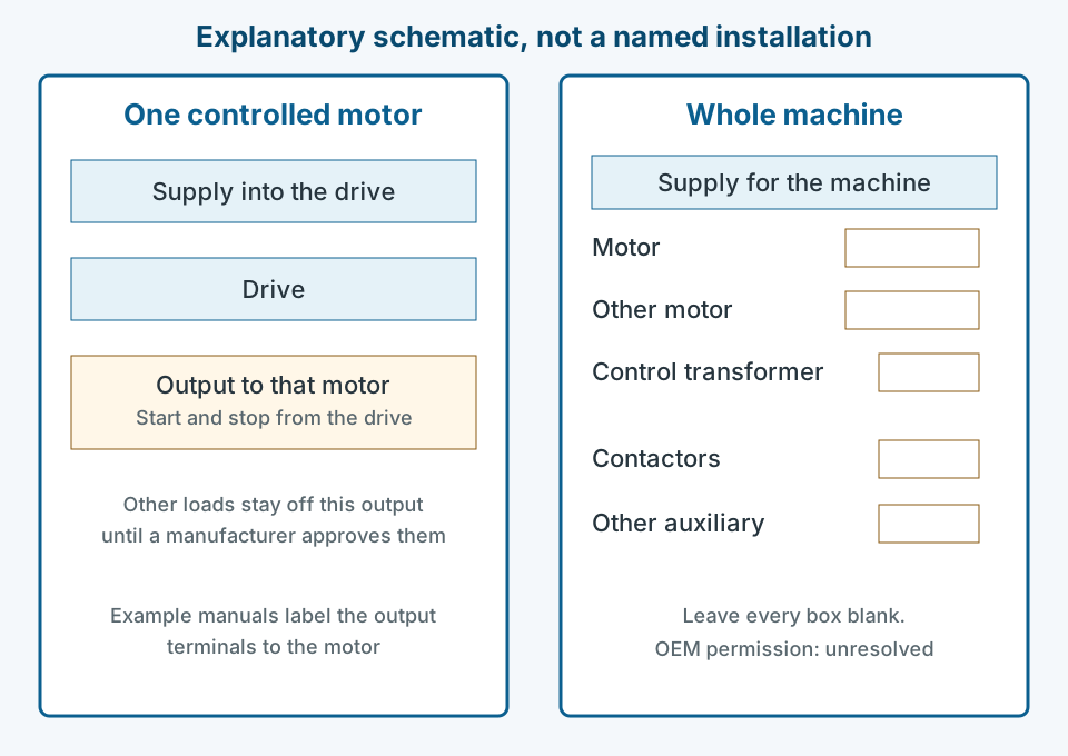
A drive and a rotary phase converter are sold for different jobs. A drive commands the speed and starting of a motor. A rotary phase converter is sold as a way to feed three-phase equipment from a single-phase service, including more than one machine when the maker sizes it for that list. This page does not rank those products, and it does not carry any converter performance figure or price.
The manual reviewed for the drive side is Rockwell Automation's PowerFlex 40P user manual, publication 22D-UM001F-EN-E, September 2024. It is one product family's document, not a rule for every drive. In that manual the output terminals U/T1, V/T2 and W/T3 are described as connections to the motor. The control method is listed as sinusoidal PWM, volts per hertz, and sensorless vector, produced with IGBTs. That is a controlled waveform for a motor. Do not use it as the general three-phase supply for a shop, a second motor, or the rest of a machine unless that drive's manufacturer says so in writing for the exact catalog number.
A 2015 AutomationDirect account by Peter James shows the one-motor pattern in a shop that did not have three-phase utility service. He fitted a separate drive to a lathe, a radial drill and a mill/drill. On each machine the drive output went to that machine's three-phase motor, and start, stop, direction and speed were taken from the drive. The account is a published description of those three installations. It is not a test run for this page, and it is not a sizing method.
Published comparisons often stop earlier than this inventory. One distributor article prefers a drive over either kind of phase converter for induction motors, and it also says a drive is typically dedicated to one machine yet can run several tools. A converter manufacturer's article describes a rotary unit as a continuous supply for several pieces of equipment. Those pages do not give you a blank for the control transformer, the contactors, or the simultaneous-start list, and their performance claims are not used here.
Takeaway: Choose the one-motor route only for the motor a drive is approved to run. Choose a machine-supply route when any other load has to stay powered.
Where do the existing contactors and the control transformer sit?
Many machines already contain contactors and a control transformer. The question is what those devices switch, and which source they expect. Guessing that a drive output can replace the supply they were wired to is how a one-motor drive gets asked to run the whole cabinet.

The same PowerFlex 40P manual draws two boundaries.
Output side. The drive is intended to be started and stopped by its control inputs. A device that routinely disconnects and then reapplies output power to the motor, for the purpose of starting and stopping, should not be used. If the motor must be disconnected while the drive is still outputting, an auxiliary contact should disable the drive's run command at the same time.
Line side. A contactor or other device that routinely disconnects and reapplies the AC line to the drive, in order to start and stop the motor, can cause drive hardware damage. The manual says the drive is designed to use control input signals. If an input device is used that way, it must not exceed one operation per minute, or drive damage can occur. That once-per-minute limit belongs to this manual. Do not copy it onto another catalog number.
A control transformer on the machine is a load in the inventory, not a detail you can skip. The isolation-transformer notes in that PowerFlex manual are line-side corrective devices for listed supply conditions, such as low line impedance or an ungrounded system. They do not rate the drive output as a source for a machine's control transformer. Whether your transformer, contactor coils, or other controls can be fed from a particular drive output is an open question for that drive manufacturer and the machine builder.
Buyer conversations often mix these locations up. People ask whether a drive is simply a phase converter, and some keep a converter because they do not want to alter the contactors already in the machine. That is a useful description of the choice. It is not an installation method, and this page does not describe how to build a converter. VFD wiring basics covers ordinary drive power and control connections after a drive has been approved for one motor.
Common mistake: Leaving the machine's motor contactors in place and letting them start and stop the motor on the drive output. In the manual above, that is the arrangement the output-disconnect paragraph says not to use for routine start and stop.
Takeaway: Map every existing contactor to the line, the drive output, or a control signal, and keep the control transformer on the inventory until someone approves a source for it.
What do you record when more than one load can start?
A machine supply has to be described as a list, not as a horsepower label on the largest motor. Write down every three-phase load and every control load that is energized with the machine. Then write the order in which they start, and mark the ones that start together.
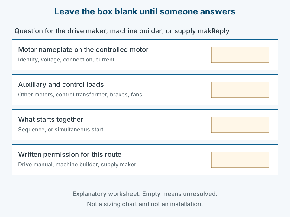
For each load, record the nameplate identity, voltage, connection and current when a nameplate exists. For a control transformer, record that it is present and what it feeds. If you do not know the current or the sequence, leave the cell blank. A blank is an unresolved item. It is not a reason to invent a ratio between the largest motor and the supply.
Converter makers ask for this list because simultaneous starting changes what the supply has to deliver. This page does not turn that list into a size. There is no universal multiple of motor horsepower here, and no claim about how a particular converter behaves under that start. The supply manufacturer, using the current documents for the product you ask about, is the one who accepts or rejects the list.
If the only load is one motor, and you are ready to command it from a drive, you still finish the single-phase input checklist when the building service is single-phase. That page owns input permission and derating. This page does not repeat those checks. Drive selection by current and duty, once the route is a single approved motor, stays in how to choose a VFD.
Takeaway: Several loads require a written list and a starting sequence. The list is not a size.
What do you ask each manufacturer?
Copy the matrix. Fill the buyer column from nameplates and a look inside the cabinet. The result column stays empty until the cited document, or a written reply, covers that row. Rejected ends that candidate. Unresolved waits.
| Check | One controlled motor | Whole-machine supply | Where the answer comes from | Result |
|---|---|---|---|---|
| 1. Motor identity, voltage, connection, current | The motor the drive will run | Every motor that stays on the machine supply | Motor nameplates | |
| 2. Auxiliary and control loads | Confirm there are none on the drive output, or list any a manufacturer has approved | Control transformer, coils, brakes, fans, heaters, other motors | Machine wiring and nameplates | |
| 3. Starting sequence | The drive's control inputs start and stop that motor | Which loads start together, and which start later | Machine builder or a timed observation you record | |
| 4. Existing contactors | None routinely switching the drive output or the line into the drive for start/stop | Contactors remain on the machine supply the builder used | Cabinet inspection, then the drive manual if a drive is still in the route | |
| 5. Drive output used only for its approved motor | Manual wording for the exact catalog number, revision and page | Not this route, unless a drive maker approves a stated extra load | Drive manual or written manufacturer reply | |
| 6. Machine builder permission | Written acceptance if OEM wiring, interlocks or a control transformer will change | Written acceptance that the machine stays on the proposed supply | Machine builder | |
| 7. Supply equipment permission | The drive's input rules, including single-phase permission on the other checklist | The converter or other supply maker's acceptance of your load list and starting sequence | That manufacturer's current document | |
| 8. Unresolved questions | Name the person and the document still open | Name the person and the document still open | Your own list | |
| 9. Sign-off | Drive manufacturer or a qualified person for the installation | Supply manufacturer, machine builder, or a qualified person | Named reviewer and date |
Swipe or scroll horizontally to see all columns.
Read row 5 and row 7 as different companies when the drive and the supply are different products. A conversation with us does not close either row. Variable frequency drives is the catalog to browse only after row 5 is approved for a specific motor. Panel layout, once a drive is the approved route, belongs with VFD panels.
Takeaway: Each route has its own reviewer. An empty result is still an open order.
What this page leaves open
- Single-phase input derating. Owned by the single-phase checklist. A footnote in one drive manual is not a ratio for the next drive, and it is not repeated here.
- Building a converter. This page does not describe parts, capacitors, idler motors, or a construction sequence.
- Brand order. No converter or drive brand is ranked. The PowerFlex manual and the 2015 shop account are examples of published documents, not a shortlist.
- Savings and universal size ratios. No payback, no horsepower multiple, and no claim that one route is always cheaper or always large enough.
- Low-speed motor heating. Speed range, torque and cooling are drive-and-motor application questions. They are not settled by calling a drive a phase converter, and this page does not publish a speed ratio.
Takeaway: An open exclusion is a stop. It is not a hint to improvise the missing rule.
Frequently asked questions
Can a VFD supply three-phase power to the whole shop?
No. Use a drive for a motor its manufacturer approves. A shop bus, a second machine, or the other loads inside one machine need a supply route and the inventory above. Drive output in the manual reviewed here is described as a PWM waveform to the motor, which is a different job from utility power.
Can the machine contactors stay between the drive and the motor?
Only if the drive manual allows that device for the way you will use it. In the PowerFlex 40P manual, a device that routinely disconnects drive output to start and stop the motor should not be used. Disconnecting the motor while the drive is outputting calls for an auxiliary contact that also drops the run command. The line contactor that cycles power into the drive has its own damage warning in that manual.
What information is required when several loads start together?
The nameplate of each motor, the other loads including a control transformer, and a note of which of them start at the same time. Take that list to the supply manufacturer. This page does not convert it into a converter size.
Who has to approve the route?
The drive manufacturer for a one-motor drive route, the machine builder when OEM wiring or a control transformer is involved, and the supply manufacturer when a converter or other machine supply is the route. More than one of those people can be required on the same machine. This page is the form, not the signature.
What to bring with the nameplates
The message section at the bottom of this page is already tied to this article. Bring the scene the inventory describes, not a horsepower guess.
| Item | What it settles |
|---|---|
| Motor nameplate | Voltage, connection and current for the controlled motor, or for each motor on a machine supply |
| Drive nameplate, if you already have a candidate | Exact catalog number for the output and contactor questions |
| Load inventory | Auxiliary loads, the control transformer, and the contactors, with blanks left blank |
| Starting sequence | What starts together |
| Documents already in hand | Manual title, publication number, revision and the page you are asking about |
Swipe or scroll horizontally to see all columns.
Open the message section and include the motor nameplate, the drive nameplate and the load inventory from this page. We can point at which matrix rows are still empty. Approval stays with the manufacturer named on that row, or with a qualified person for your installation.
Editorial basis
Reviewed 12 October 2026. This comparison uses public documents. It is not a test, a certification, or an approval of any drive or converter. Figures from one manual stay with that manual.
- Rockwell Automation PowerFlex 40P User Manual, publication 22D-UM001F-EN-E — September 2024. Cited for the output-terminal description, the PWM control method, the output-disconnect paragraph, and the line-contactor attention. Not a product recommendation, and not a rule for other catalog numbers.
- AutomationDirect, Converting a Mill/Drill and Installing a VFD, Issue 33 — Peter James, 3 September 2015. Cited only as a published account of one drive per machine motor. Performance sentences in that account are not used.
Drive output rules, converter capacity and machine wiring differ by exact product and by the machine builder's instructions. Confirm every matrix row against the current document for the equipment you intend to buy.