
Technical guide
VFD Braking Resistor Selection: Resistance, Energy and Duty Checks
Size a VFD braking resistor as three separate checks: the resistance the drive allows, the energy of each stop and the duty it repeats, then record the source of each.
Jack Dean writes practical VFD selection, wiring, replacement and power-quality guides using current manufacturer documentation and explicit procurement checks.
Author profile
A braking resistor below the drive's printed minimum resistance draws more current than that limit permits, and a resistor rated only for occasional stops can overheat on a machine that stops every cycle. A braking resistor is sized by three separate checks: the resistance the drive allows, the energy and peak power of each stop, and the duty the resistor can repeat without overheating. This page covers dynamic braking of one VFD into an external resistor and gives you a blank duty record to fill from the drive manual and the resistor datasheet, instead of a number to copy.
Short answer: to size a braking resistor, start from the drive, not the motor. Read the minimum resistance for your exact drive rating from its manual and confirm whether the brake transistor (the chopper) is built in. Then describe the stop: the speeds, the stop time, how often it repeats and whether the load is decelerating or overhauling. A resistor supplier turns that description into a resistance band, a power rating and a duty rating. In the 2024 drive manual we read, the resistors in the selection table are rated for a 5% duty cycle, so a machine whose braking takes a larger share of its cycle needs a different resistor and a matching drive setting. Leave each value blank until a document gives it.
This is a buyer's record for the VFD Learning Center, not a braking calculation. The resistance cells in the manuals we read belong to those manuals and are not reprinted here.
| Input or record | Where the value comes from | Why it matters |
|---|---|---|
| Drive nameplate | Complete catalog number and input voltage; manual publication and revision | The minimum-resistance table is printed per input voltage and drive rating |
| Brake chopper | The drive manual's power-terminal table | A resistor needs a brake transistor and the terminals that serve it |
| Reason for braking | The overvoltage fault record, the required stop time or a load that drives the motor | It decides whether a resistor is needed or a longer ramp is enough |
| Stop description | Speeds, stop time, braking time and cycle time from the machine sequence | Energy per stop and repeat duty are calculated from these |
| Regeneration type | Decelerating a moving load, or holding back an overhauling load | The resistor supplier sizes the two types differently |
| Resistor rating | The resistor datasheet: resistance, power and duty cycle | The drive's protection setting has to match this duty |
| Thermal protection | The resistor datasheet and the protective circuit in the drive manual | The manual we read warns of a fire risk without it |
| Still open | Whatever supplier or manufacturer confirmation is not yet in hand | An open row is a valid result |
Swipe or scroll horizontally to see all columns.
Does the drive need a braking resistor at all?
Only if a longer deceleration is not acceptable. When a motor slows a load, or a load drives the motor, the motor returns energy to the drive's DC bus. The 2024 drive manual we read lists bus overvoltage as a fault that motor regeneration can cause, and gives two remedies: extend the deceleration time, or install the dynamic brake option.
The same manual describes a third path and its cost. Its bus regulator prevents nuisance overvoltage faults from aggressive deceleration, overhauling loads and eccentric loads, but the actual deceleration can then take longer than the time you set, and the drive raises a stall fault if it stays in that state for 1 minute. The manual says a properly sized dynamic brake resistor gives equal or better performance in most cases.
So the first row of the record is the reason. If the fault log shows bus overvoltage on stops and the process can accept a slower stop, a longer ramp may settle it. If the stop time is fixed by the machine, or the load keeps driving the motor, record that and continue.
Check for a chopper. A resistor dissipates energy only when a brake transistor switches it onto the DC bus. The manual we read lists a pair of dynamic brake resistor terminals on that drive. Read the power-terminal table in the manual for your catalog number.
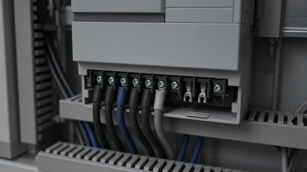
If the terminal table shows no brake transistor, the record needs an external braking unit as well, and that unit has its own documents. The VFD wiring basics guide explains why a braking terminal label cannot be read across from a similar-looking drive.
Takeaway: Record why braking is needed and whether the drive has a chopper before anyone quotes a resistor.
What resistance is the resistor allowed to have?
The lower limit comes from the drive manual. The manual we read prints a minimum resistance for each input voltage class and drive rating, in ohms, next to a listed resistor and the fuses for its terminals. At a given DC-bus voltage, a lower resistance draws more current and gives stronger braking. One resistor supplier's sizing page says the same and warns not to exceed the drive's braking current. The minimum in the table is the drive's limit, not a suggested value.
The upper limit is a different question. A resistance that is too high cannot take the peak power of the stop you described. The manual we read does not print a maximum. It says resistors other than the listed ones may be used with care and refers to a separate resistor-calculation publication, which we did not read. So the approved resistance band in the record has two sources: the minimum from the manual, and the upper value from the resistor supplier's or drive maker's calculation for your stop.
Two more details from that table belong in the record. For one drive rating the listed resistor is two resistors wired in parallel, so the record notes the combined resistance, not the label on one unit. And the fuse columns apply to the resistor terminals; for IEC applications, the manual makes a DC fuse mandatory when those terminals are connected, placed close to the terminal.
Takeaway: Write the minimum resistance from the manual cell for your catalog number, and leave the upper value open until a calculation for your stop gives it.
How much energy does each stop return, and how often?
Energy per stop, peak power and repeat duty are three requirements, and a resistor can meet one and fail another. Record each one separately.
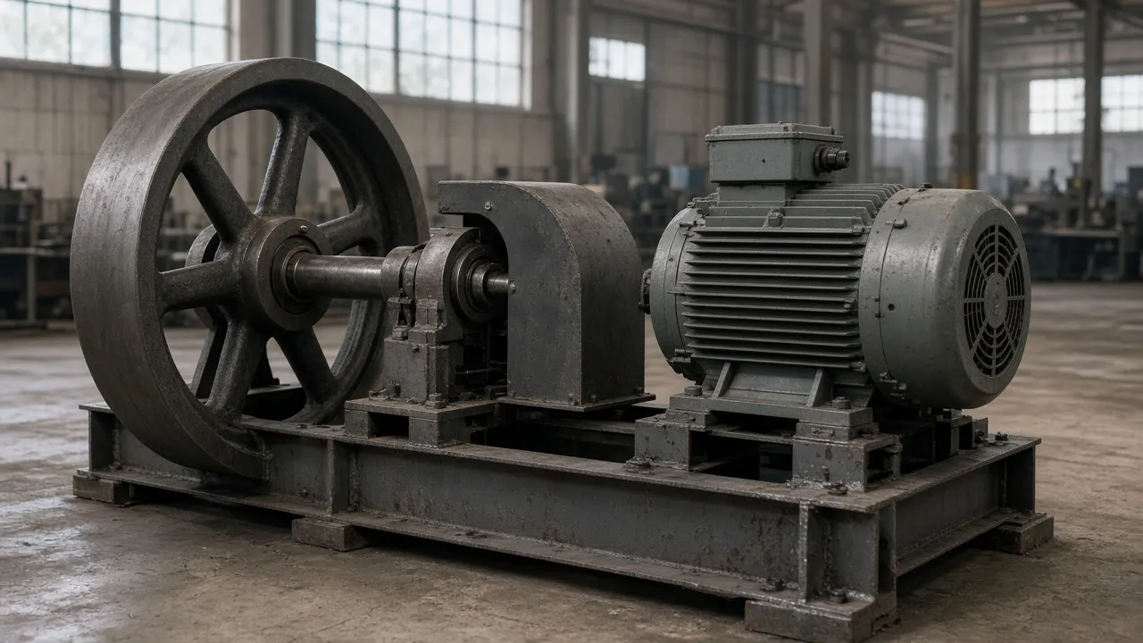
- Energy per stop. It depends on how much the moving parts store and how far the speed falls. Write the load or inertia source (a drawing, a motor-and-gearbox datasheet, or "not known") and the speed at the start and end of the stop.
- Peak power. It is highest when the stop begins and depends on the resistance and on the DC-bus voltage at which the chopper switches. Your stop time sets how fast the energy has to leave.
- Repeat duty. A resistor that survives one stop can overheat if the next stop comes before it cools. One resistor supplier defines duty cycle as braking time divided by cycle time. Record both times from the machine sequence, not an estimate of "a few stops an hour."
Regeneration type. The same supplier sizes a decelerating load and an overhauling load (one that keeps driving the motor, such as a lowering load) with different methods, and asks which one applies. Write which one applies to your machine. If a single cycle contains both, write both with their times.
The supplier's published list of inputs is a useful check that the record is complete. It asks for the drive input voltage and power, the braking torque, the duty cycle with on and off times, the maximum braking current or minimum resistance stated by the drive manufacturer, the regeneration type, and the enclosure type. Each of those is a row in the record below.
Takeaway: A resistor is not chosen from the motor's kW. It is chosen from the stop: speeds, stop time, cycle time and regeneration type.
What duty cycle is the resistor rated for, and does the drive protect it?
The duty rating on the resistor has to match the duty the machine asks for and the protection setting in the drive. In the 2024 drive manual we read, the resistors in the selection table are rated for a 5% duty cycle. Its resistor-selection parameter has four kinds of setting: disabled; the listed resistors at 5% duty; no protection at 100% duty; and a limited duty from 3% to 99%. With the listed setting and a suitable resistor, the drive provides calculated resistor overload protection. The manual also says the drive cannot protect against a brake transistor failure.
Two consequences follow for the record. A machine whose braking time is a larger share of its cycle than the listed resistor's rating needs a resistor rated for that duty and a drive setting that matches it, not the table's resistor at its table setting. And the same manual warns that setting the brake's DC-bus switching threshold below its default has to be evaluated so the resistor's wattage rating is not exceeded, especially when protection is turned off.
Takeaway: Record the resistor's duty rating and the drive's protection setting on the same line. A mismatch between the two is the most likely reason a correctly sized resistor still overheats.
How is the resistor protected and mounted?
The manual we read warns that a fire risk exists if an external braking resistor is not protected: the resistor package must protect itself from overtemperature, or a protective circuit must be supplied. The circuit it recommends places a thermostat on the resistor in the control circuit of the drive's input contactor. Our reading: because the drive cannot protect against a brake transistor failure, that external circuit is what is left if the transistor fails.
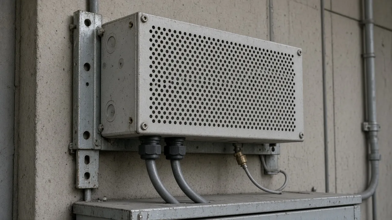
Record the thermal device on the resistor datasheet (a thermal switch or thermostat, or "none"), how it is wired into the control circuit, and the enclosure type. The resistor supplier we read offers a thermal switch on request, so it is a line item to ask for, not an assumption. Placement matters too: keep the resistor's heat away from the drive and nearby materials, as the VFD wiring basics guide explains.
The same manual adds a stopping limit that a resistor cannot fix. If a hardwired stop removes AC power from the drive, any regenerative braking is lost and the motor coasts to a stop, so an auxiliary braking method may be required. Where movement of equipment or material can cause injury, the manual requires an auxiliary mechanical braking device. Those requirements belong to the machine's safety design, not to this record.
Takeaway: The thermal row is filled only when the resistor's thermal device and the circuit it trips are both written down.
The braking duty record
Copy this record and fill it from the documents you have. Every blank cell is intentional. A blank cell is not a result, and an open row is a valid outcome. Write the source for each entry: the publication number, revision and page, the datasheet, or the date and sender of a written reply.
| Row | What you write | Empty until | Your entry | Source (document, revision, page or reply) | Status (filled / open) |
|---|---|---|---|---|---|
| 1. Drive nameplate | Complete catalog number, input voltage, manual publication and revision | A family name is not a row | |||
| 2. Brake chopper | Built in, external braking unit, or none; the terminals named in the manual | The power-terminal table is read | |||
| 3. Reason for braking | Overvoltage fault record, required stop time, or overhauling load | "Longer ramp not acceptable" is written down | |||
| 4. Load or inertia source | Drawing, datasheet or "not known" | A document exists | |||
| 5. Speeds | Speed at the start and end of the stop, with unit | Taken from the machine sequence | |||
| 6. Stop time | Required stop time, with unit | Set by the process, not by a guess | |||
| 7. Braking and cycle time | Braking time and cycle time, or the interval between stops | Both times are known | |||
| 8. Regeneration type | Decelerating, overhauling, or both with their times | The load is described | |||
| 9. Minimum resistance | The manual cell for the drive rating in row 1 | The cell for this catalog number is read | |||
| 10. Approved resistance band | Minimum from row 9; upper value from the supplier's or drive maker's calculation | A calculation for this stop exists | |||
| 11. Resistor rating | Resistance, power and duty cycle from the resistor datasheet; parallel units noted | A datasheet is in hand | |||
| 12. Drive protection setting | The resistor-selection setting that matches row 11's duty | Rows 7 and 11 agree | |||
| 13. Thermal protection | Thermal device on the resistor and the circuit it trips | "None" stays open | |||
| 14. Fuses | Fuses for the resistor terminals named in the manual | The manual's fuse columns are read | |||
| 15. Mounting and enclosure | Enclosure type and location relative to the drive | The location is chosen | |||
| 16. Supplier confirmation | Written confirmation that rows 9 to 13 fit the stop in rows 5 to 8 | A dated written reply | |||
| 17. Still open | Every confirmation not yet in hand | An open cell is a valid result |
Swipe or scroll horizontally to see all columns.
Read it simply. Rows 1 and 2 decide whether a resistor can be fitted at all. Rows 4 to 8 describe the stop. Rows 9 to 12 are the resistor and the drive setting that must fit that stop, and rows 13 to 15 keep it safe. If row 16 is empty, the resistor is not yet approved. Neither this page nor a conversation with us replaces the supplier's or drive manufacturer's written answer.
The how to choose a VFD guide asks for the deceleration and braking requirement when you describe an application; this record is how that requirement is documented. If you are replacing a drive that already has a resistor, the VFD replacement checklist explains why the old resistor cannot simply move to the new drive's terminals. Once the record shows a resistor class and rating, our power quality products page lists braking resistors and braking units as a hardware category. It is a catalog, not an approval of a resistor for your stop.
Takeaway: The record is finished when every row has a source or an honest "open." It is not finished when someone has copied a resistance from another drive.
When this does not apply
- Holding brakes and load holding. A braking resistor slows a motor through the drive; it does not hold a stopped load. Mechanical brakes are outside this record.
- Hoists and other safety-critical motion. Where movement can injure someone, the braking design belongs to the machine's safety engineering.
- DC injection braking. It is a drive stop mode, not a resistor. The manual we read says it should not be used with synchronous or permanent-magnet motors, which can be demagnetized during braking.
- Regenerative units and active front ends. Returning energy to the supply is a different product with its own documents.
- Resistor terminal wiring. Terminal, grounding and cable layout belong to the wiring guide linked above and the exact drawing for your drive.
- A universal motor-kW formula. This page does not size a resistor from motor power alone.
Frequently asked questions
How do you calculate a dynamic braking resistor for a VFD?
Start from the drive's minimum resistance in its manual, then calculate the energy, peak power and duty of your stop from rows 4 to 8 of the record. The calculation belongs to the resistor supplier or the drive maker; this record makes sure every input is written down.
What is dynamic braking on a VFD?
The drive's brake transistor switches a resistor onto the DC bus when the motor returns energy, and the resistor turns that energy into heat. It lets the drive stop a load faster than its overvoltage limit would otherwise allow, and it needs a chopper in or beside the drive.
What to send us
If you want a second look at the record, send what you already have. Unknown or not yet measured is fine; mark it that way.
| Item | Why we need it | Example format |
|---|---|---|
| Drive nameplate | The minimum resistance and chopper belong to the complete catalog number | Photo or full catalog string |
| Stop description | Speeds, stop time, braking time, cycle time and regeneration type | Values with units, or "not known" for each |
| Load or inertia source | Energy per stop depends on it | Drawing, datasheet, or "not known" |
| Existing resistor, if any | Resistance, power, duty and thermal device must fit the new stop | Datasheet or photo of the resistor's rating plate |
| Partly filled record | Shows which rows are still open | Copy of the record above |
Swipe or scroll horizontally to see all columns.
Send these records through WhatsApp. We read them and tell you which rows of the record are still open, and whether a document you hold is the manual for that nameplate. We do not approve a resistance, a duty rating, a price or a ship date; the resistor approval stays with the resistor supplier, the drive manufacturer and the qualified person responsible for the machine.
Editorial basis
Reviewed 14 October 2026. This record is compiled from public documents. It is not a test, a measurement, a calculation or an approval of any drive or resistor, and the resistance cells in these documents are specific to the drives they cover, so they are not reprinted here.
- Drive user manual, publication 22D-UM001F-EN-E, September 2024 — read for its overvoltage fault remedies, bus-regulator caution, brake terminals, resistor-selection parameter, switching-threshold caution, minimum-resistance and fuse table, and recommended resistor protection circuit. Its values apply to the drives it covers only.
- A resistor supplier's published dynamic-braking sizing page, read 11 October 2026 — cited only for the inputs it asks buyers to provide and its definition of duty cycle. Its sizing method and figures remain that supplier's own.
Braking limits, protection settings and resistor ratings differ by exact catalog number, firmware and machine. Confirm every row against the current manual for the drive on your nameplate.