
技术指南
VFD Installation Cost: Compare the Scope Before Comparing Quotes
Compare VFD installation quotes by auditing missing enclosure, reactor, shielded cable, safety, and startup scope that causes rework and unplanned downtime.
Jack Dean 基于制造商当前资料和明确的采购核对项,撰写 VFD 选型、接线、替换及电能质量实用指南。
查看作者资料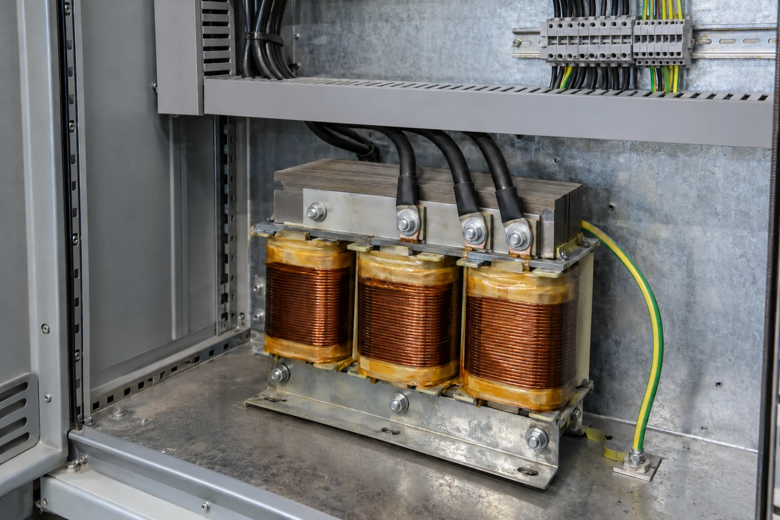
Comparing two variable frequency drive proposals by bottom-line total alone hides missing enclosure cooling, input line reactors, shielded motor cabling, and commissioning tasks that trigger change orders, equipment damage, or startup downtime. Before comparing commercial figures, buyers must align every bidder against a single installation scope record so that an open-chassis box quote is never mistaken for a complete, commissioned drive system.
Published VFD price lists typically cover only the bare drive module, while simplified energy calculators routinely exclude variable installation labor, harmonic mitigation hardware, and plant outage windows. Whether a project involves a compact wall-mounted drive or a custom multi-section cabinet from our VFD control panels range, total installed cost is governed by eight distinct hardware and field-service boundaries that depend on the exact drive manual, supply transformer, cable route, and driven machine.
Why VFD Installation Quotes Diverge on the Same Motor
When two electrical contractors, panel shops, or automation integrators quote a VFD installation for the same motor nameplate, the commercial gap rarely comes from the base inverter markup alone. It comes from unstated assumptions about where the supplier's scope stops and where the plant's responsibility begins.
| Cost & Scope Layer | What a Bare-Drive or Minimal Quote Covers | What a Complete Installed System Quote Covers | Where to Verify the Requirement |
|---|---|---|---|
| 1. Base drive & option cards | Open-chassis (IP20) or standard NEMA 1 drive sized to nominal horsepower only | Drive sized to continuous Full Load Amps (FLA) and overload duty, plus remote keypad/HIM, fieldbus adapter, deeper frame cover, and Safe Torque Off (STO) board | Motor nameplate FLA, duty profile (constant vs. variable torque), and drive catalog option tables |
| 2. Enclosure & thermal management | Assumes the buyer already has a clean, cool electrical room with spare backplate space | NEMA 12, NEMA 3R, or NEMA 4/4X enclosure sized to minimum volume/clearances, or forced-air filtered fans, heat exchangers, or cabinet air conditioning plus anti-condensation heater | Drive manual thermal dissipation rating (typically 2% to 5% of load power) and plant ambient environment |
| 3. Input power & branch protection | Terminal landing on an existing breaker with no impedance or fault-current check | Door-interlocked disconnect, UL Class J/CC/T fuses or UL489 breaker, 3% or 5% input line reactor, isolation transformer, or IEEE 519 harmonic filter, plus ungrounded supply MOV configuration | Upstream distribution transformer kVA, available short-circuit current (SCCR), and grounding type |
| 4. Output filtering & braking | Direct output termination to existing motor leads; coast-to-rest stopping | Output load reactor, $dV/dt$ filter, or reflected-wave terminator for long motor runs; external dynamic braking resistor with thermal overload relay and upstream trip contactor | Actual routed cable length to motor, motor insulation class, and load deceleration inertia/cycle time |
| 5. Cabling, glands & raceways | Reusing existing unshielded conduit wiring or landing customer-pulled leads | Symmetrical shielded VFD motor cable, 360-degree EMC grounding glands at panel and motor box, and physical separation (>= 0.3 m / 1 ft) between power/motor and control/encoder trays | Drive installation manual wiring rules, NEC/IEC local code, and physical conduit routing walkdown |
| 6. Control, safety & PLC integration | Local keypad start/stop only | Hardwired permissive interlocks, emergency-stop / Safe Torque Off loop, 4–20 mA / 0–10 V analog scaling, and Ethernet/IP, Modbus, or Profibus PLC tag mapping and fault logic | P&ID control philosophy, machine risk assessment, and existing PLC/SCADA architecture |
| 7. Commissioning & acceptance testing | Apply power and verify the display lights up | Pre-power megger test (drive disconnected), motor voltage jumper check, nameplate entry, static/rotating auto-tune, uncoupled rotation test, coupled full-load current/thermal check, and parameter file backup | Manufacturer startup checklist and site commissioning acceptance protocol |
| 8. Outage logistics & handover | Standard weekday shift access; no documentation package | Scheduled shutdown cutover labor, LOTO coordination, crane/rigging for floor cabinets, redline as-built schematics, spare fuses/fan filters, and operator/maintenance training | Plant production schedule, maintenance turnover standards, and site safety rules |
横向滑动或滚动以查看所有列。
Key takeaway: Never compare two VFD installation bids until both suppliers confirm in writing which of the eight layers above are included, excluded, or carried as a rough allowance.
Copy-Ready VFD Installation Quote Scope Comparison Table
Use the blank comparison table below during bid leveling or attach it to your Request for Quotation (RFQ). Leave the supplier amount columns blank when issuing the sheet so each bidder fills in their own pricing alongside explicit inclusion status, technical basis, and task ownership.
| Scope Line Item | Spec / Quantity / Unit | Quote A Amount (Blank) | Quote B Amount (Blank) | Included / Excluded / Allowance | Source of Requirement | Responsible Party (Vendor / Contractor / Plant) | Unresolved Bid Questions |
|---|---|---|---|---|---|---|---|
| 1. Base VFD unit (frame, voltage, continuous FLA & overload rating) | [ ] qty / [ ] A continuous / [ ] % 60s overload | [ ] Inc [ ] Exc [ ] Allow | Motor nameplate FLA & constant vs. variable torque duty | Is the frame sized for continuous amps at max ambient without derating? | |||
| 2. Drive option cards & mounting kits (HIM, fieldbus, STO, conduit box, deeper cover) | [ ] keypad kit / [ ] comm card / [ ] STO board | [ ] Inc [ ] Exc [ ] Allow | Control architecture & drive manual accessory compatibility rules | Does adding a comm adapter require a deeper frame cover or bezel kit? | |||
3. Enclosure assembly & environmental rating (IP20, NEMA 1, 12, 3R, 4/4X) | [ ] rating / [ ] H×W×D mm or in. | [ ] Inc [ ] Exc [ ] Allow | Installation location (clean room, dusty shop floor, washdown, outdoor) | Is the drive open-chassis, flange-mounted, or inside a sealed cabinet? | |||
| 4. Cabinet cooling & condensation control (fans, heat exchanger, AC unit, space heater) | [ ] W heat load / [ ] °C max ambient | [ ] Inc [ ] Exc [ ] Allow | Drive watt-loss rating (2%–5% of load) & minimum unventilated volume table | Who supplies power and thermostat interlocks for cabinet cooling or space heaters? | |||
| 5. Branch circuit protection & main disconnect (fuses, UL489 breaker, combination starter) | [ ] A rating / [ ] kA SCCR | [ ] Inc [ ] Exc [ ] Allow | Drive manual fuse/breaker table & plant fault-current study | Does the quoted assembly meet the required panel Short-Circuit Current Rating (SCCR)? | |||
6. Input power conditioning (3% or 5% AC line reactor, DC choke, isolation transformer, harmonic filter) | [ ] % impedance / [ ] A rating / internal vs. external mount | [ ] Inc [ ] Exc [ ] Allow | Supply transformer kVA (>10x drive kVA), voltage unbalance, or IEEE 519 target | Is the distribution bus grounded wye, high-resistance grounded, or ungrounded delta? | |||
| 7. Bypass contactor arrangement (none, manual 2-contactor, automatic 3-contactor bypass) | [ ] configuration / [ ] enclosure section | [ ] Inc [ ] Exc [ ] Allow | Process redundancy requirement during drive maintenance | Are bypass overload relays and electrical/mechanical interlocks included? | |||
8. Output motor protection (dV/dt filter, output load reactor, reflected-wave device, sine filter) | [ ] routed cable length (m or ft) / [ ] V peak limit | [ ] Inc [ ] Exc [ ] Allow | Drive manual reflected-wave cable table & motor insulation class (1000V vs. 1488V+) | Is the output filter mounted inside the main panel or in a separate vented box? | |||
| 9. Dynamic braking resistor & thermal protection circuit (resistor bank, thermal overload, upstream trip contactor) | [ ] Ohms / [ ] W continuous / [ ] % duty cycle | [ ] Inc [ ] Exc [ ] Allow | High-inertia deceleration or overhauling load duty cycle | Does the quote include the upstream input contactor wired to the resistor thermal trip switch? | |||
| 10. Motor power cable, 360° EMC glands & raceway installation | [ ] m or ft shielded VFD cable / [ ] gland qty / [ ] conduit size | [ ] Inc [ ] Exc [ ] Allow | Drive EMC installation guide & physical route from panel to motor box | Are symmetrical shielded VFD cables and 360-degree grounding clamps included at both ends? | |||
| 11. Control, feedback & safety wiring segregation | [ ] m or ft control run / [ ] separate conduit or tray divider | [ ] Inc [ ] Exc [ ] Allow | Drive manual minimum separation rule (>= 0.3 m / 1 ft from power cables) | Are encoder, 4–20 mA, and 24 VDC permissive wires routed in a dedicated metallic raceway? | |||
| 12. Hardwired safety & emergency-stop integration | [ ] safety relay / [ ] STO channel wiring | [ ] Inc [ ] Exc [ ] Allow | Machine safety rating (EN ISO 13849-1 / SIL) & drive manual hardware-enable rule | Does the E-stop use certified Safe Torque Off or an upstream contactor instead of software stop? | |||
| 13. PLC / SCADA / BMS programming & HMI faceplate updates | [ ] I/O points / [ ] fieldbus words / [ ] HMI screens | [ ] Inc [ ] Exc [ ] Allow | Plant control specification & fault/speed reference handover | Who writes and tests the PLC communication logic, scaling, and fault interlocks? | |||
| 14. Pre-energization testing (megger test, motor jumper verification, torque check, supply unbalance check) | [ ] test records / [ ] motor terminal inspection | [ ] Inc [ ] Exc [ ] Allow | Manufacturer pre-power checklist & warranty validation conditions | Will motor leads be meggered before landing on the drive and checked for 230V/460V jumper position? | |||
| 15. On-site startup commissioning (nameplate entry, auto-tune, uncoupled rotation, coupled full-load & thermal check) | [ ] service days / [ ] shifts | [ ] Inc [ ] Exc [ ] Allow | Drive startup manual & process performance acceptance criteria | Does commissioning include both an uncoupled rotation/auto-tune test and a coupled full-load run? | |||
| 16. Outage tie-in, parameter backup, as-built drawings & training | [ ] outage window / [ ] parameter file / [ ] redline drawings | [ ] Inc [ ] Exc [ ] Allow | Plant maintenance handover standard | Are parameter files exported (e.g., CCW / software backup) and redline schematics delivered at sign-off? |
横向滑动或滚动以查看所有列。
Technical Triggers That Turn "Optional" Hardware Into Mandatory Scope
A frequent source of post-award disputes is when a bidder labels line reactors, output filters, braking hardware, or enclosure cooling as "optional" without checking the site conditions that make them mandatory in the drive manual. Use the engineering triggers below—drawn from manufacturer installation manuals such as the Allen-Bradley PowerFlex 40P User Manual (Publication 22D-UM001F-EN-E), Rockwell Automation application paper 150-WP007A-EN-P, and standard industrial VFD application checklists—to verify whether a low bid has omitted required hardware.
An input AC line reactor or output filter mounted on the enclosure subpanel adds both component cost and cabinet footprint—plus additional heat dissipation that the panel cooling design must remove.
1. Input Line Reactors, Isolation Transformers, and Ungrounded Supplies
An open variable frequency drive quote often assumes clean, balanced utility power on a solidly grounded wye transformer sized closely to the drive. In practice, manufacturer input power conditioning tables (such as 22D-UM001F-EN-E Table 3) require an input line reactor (typically 3% or 5% impedance) or isolation transformer whenever any of the following site conditions exist:
- High upstream transformer capacity: The AC distribution source kVA is more than 10 times the input kVA rating of the VFD, or available short-circuit current exceeds the drive's bare input threshold.
- Line imbalance or transient disturbances: Reactive power factor correction capacitors are switched on the same bus, or resistive/inductive load switching creates phase imbalance exceeding 5% of the largest load.
- Harmonic distortion limits (
IEEE 519): When the plant must meetIEEE 519current distortion targets at the Point of Common Coupling (PCC), a simple 6-pulse drive without a 3%/5% AC line reactor, DC link choke, active/passive harmonic filter, or 12-/18-pulse phase-shifting rectifier will not comply. You can compare these options in our power quality products section and our technical guide on VFD harmonics and line reactors. - Ungrounded or impedance-grounded distribution systems: Many industrial plants operate ungrounded delta, corner-grounded, or high-resistance grounded feeders. Standard VFDs include internal phase-to-ground Metal Oxide Varistors (MOVs) for surge suppression; on ungrounded systems, the manual requires disconnecting the internal MOV ground jumper (and often adding an isolation transformer) to prevent continuous phase-to-ground conduction and catastrophic drive damage. If a quote ignores the feeder grounding type, that risk lands on the buyer at first energization.
2. Motor Cable Length and Output $dV/dt$ or Reactor Limits
Pulse-width modulated (PWM) IGBT outputs switch fast enough to create reflected-wave voltage spikes on long motor cables. When those voltage peaks exceed the motor winding insulation rating, premature turn-to-turn insulation failure follows—field commissioning reports from KEB America document multiple motors burning out within weeks on 300 ft unmitigated cable runs.
Manufacturer manuals publish strict cable length tables that vary by supply voltage, motor insulation rating, and output mitigation hardware. For example, in the PowerFlex 40P manual (22D-UM001F-EN-E Table 5) for 380–480V three-phase drives connected to motors with 1488 Vpk insulation:
- Bare drive only: Maximum shielded motor cable run is 15 m (49 ft) across small frame ratings.
- Drive with reflected-wave terminator (
1204-RWR2-09-B/C): Maximum shielded motor cable run increases to 40 m (131 ft). - Drive with output load reactor (
1321-3R...): Maximum shielded motor cable run increases to 170 m (557 ft) on compatible ratings.
If your conduit route from the electrical room to the motor terminal box is 45 m (150 ft) and one bidder prices a bare drive while another includes an output reactor or $dV/dt$ filter, the cheaper bid is incomplete unless the drive manual explicitly permits that cable length without external filtering. Review our VFD motor cable length checklist to record the exact manual limits for your route.
3. Enclosure Rating, Clearances, and Heat Dissipation
A VFD operates at roughly 95% to 98% efficiency, which means 2% to 5% of the controlled load power is released as heat inside the mounting space (Rockwell 150-WP007A-EN-P). Adding an internal 3% line reactor, an output $dV/dt$ filter, or a control transformer increases that cabinet watt loss further.
When comparing quotes, check how each supplier handles the physical enclosure:
- Open
IP20chassis vs. conduit box vs. sealed cabinet: AnIP20drive is built to mount inside an existing control panel. Converting an open compact drive to standaloneIP30 / NEMA 1 / UL Type 1wall mounting requires ordering the manufacturer's conduit box kit (such as22-JBABor22-JBCBon PowerFlex 40P Frame B/C), and adding a communication adapter (22-COMM-E/D/P) can require a deeper frame cover (22D-CCBor22D-CCC). - Minimum unventilated volume and clearances: If a drive is placed inside a non-ventilated
NEMA 12(dust-tight) orNEMA 4/4X(washdown/outdoor) enclosure, the cabinet must meet the drive manual's minimum internal volume and vertical clearance rules (for instance, PowerFlex 40P Table 4 specifies1.6 m³to5.4 m³minimum unventilated enclosure volume and76.2 mm / 3.0 in.to120.0 mm / 4.7 in.minimum top and bottom clearance). - Forced ventilation vs. closed-loop cooling vs. flange mounting: Where cabinet volume is compact or shop ambient temperatures approach
40 °Cto50 °C, the quote must include filtered intake/exhaust fans, an air-to-air heat exchanger, a flange-mount kit that puts the drive heatsink outside the cabinet backplane, or a dedicated panel air conditioner.
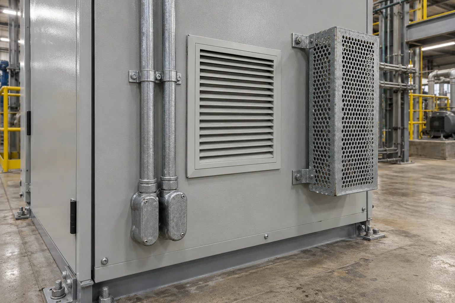
External panel hardware—such as rigid conduit hubs, filtered ventilation louvers, and stand-off perforated guards for external braking resistors—must be specified upfront so panel fabrication and field installation quotes align.
4. Dynamic Braking Protection and Hardwired Safety Circuits
Two safety-critical subsystems are frequently left out of preliminary quotes:
- Dynamic braking resistor + thermal trip circuit: High-inertia fans, centrifuges, conveyors, and overhauling loads regenerate energy onto the DC bus during deceleration. Sizing the external braking resistor requires checking minimum ohms, peak braking power, and repeat duty cycle (covered step by step in our VFD braking resistor selection checklist). Just as important, manufacturer wiring diagrams (
22D-UM001F-EN-EFigure 15) require a thermal overload switch on the resistor wired in series with an upstream three-phase input contactor (M1) so that if the internal brake chopper IGBT fails shorted, AC line power is disconnected before the resistor overheats. - Emergency stop and Safe Torque Off (
STO): Drive manuals explicitly state that software stop commands and basic digital inputs are not rated for emergency stopping. Furthermore, repeatedly dropping an upstream AC line contactor to start and stop the motor can damage the drive's DC bus pre-charge circuit. A compliant quote must include either a properly interlocked emergency-stop drop circuit or a certified Safe Torque Off option module (such as the DriveGuard20A-DG01board rated toEN ISO 13849-1 PLd Category 3).
Key takeaway: Every time a quote marks reactors, output filters, enclosure cooling, braking protection, or safety cards as "excluded," verify the exact trigger in the drive manual before treating that exclusion as a genuine saving.
Hidden Labor, Cabling, and Commissioning Exclusions That Create Change Orders
Even when two quotes list identical VFD catalog numbers, field installation and startup scope can differ substantially. Review our VFD wiring basics guide alongside the contractor's scope of work to catch the four most common field exclusions.
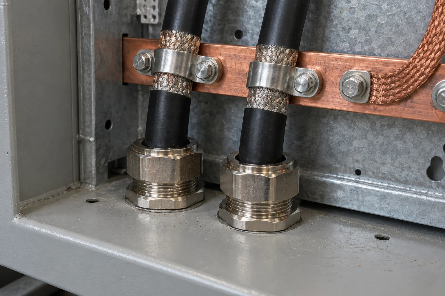
Terminating symmetrical shielded VFD cable with 360-degree EMC grounding clamps at the enclosure entry plate takes specialized cable, glands, and labor that generic electrical bids often omit.
1. Shielded VFD Cable, 360° EMC Glands, and Raceway Separation
Standard building wire (THHN/THWN) pulled through shared cable trays is a leading cause of nuisance ground-fault trips, bearing currents, and 4–20 mA or encoder signal dropouts. Proper VFD installation requires:
- Symmetrical shielded VFD motor cable terminated with 360-degree EMC cable glands or grounding saddle clamps at both the VFD panel entry and the motor terminal box.
- Control cable shields bonded to ground at one end only (typically the VFD end) to prevent ground loops.
- Physical segregation of at least 0.3 m (1 ft)—or dedicated metallic conduits—between high-voltage AC/motor leads and low-voltage 24 VDC digital I/O, analog speed references, and encoder feedback cables (
22D-UM001F-EN-E).
2. Pre-Power Insulation Testing and Motor Terminal Block Verification
Before energizing a new or retrofit VFD, the installer must verify the motor winding and feeder integrity:
- Megger (insulation resistance) testing of the motor and output cable must be performed before landing the leads on the VFD output terminals (
U/T1,V/T2,W/T3) or $dV/dt$ filter so test voltage never enters the drive power bridge. - Dual-voltage motor jumper inspection: On dual-voltage motors (
230/460V), failing to open the motor terminal box to confirm the Wye/Delta jumper links match the VFD output voltage is a documented cause of immediate startup failure (KEB America 2025).
3. Uncoupled Auto-Tune vs. Coupled Full-Load Commissioning
A complete startup service scope is not a 15-minute keypad check. A structured commissioning Scope of Work (SOW) requires two distinct phases:
- Static & uncoupled startup: Verify incoming phase-to-phase voltage balance and DC bus voltage, enter exact motor nameplate parameters (volts, FLA, Hz, base RPM, kW/HP), configure electronic motor overload (
I²t) and carrier frequency limits, run a static or rotating motor identification (auto-tune), and jog the motor uncoupled at low speed (e.g., 5 Hz) to confirm rotation direction without risking driven machinery. - Coupled full-load & thermal verification: Couple the driven load, ramp through the operating speed range, check for mechanical resonance (setting skip frequencies if needed), measure phase currents with a true-RMS meter, verify that input/output reactors stabilize within thermal limits, test PLC/SCADA speed tracking and safety interlocks, and export a parameter backup file using software such as Connected Components Workbench (
1203-USB) or keypad memory.
How to Level Competing Proposals Before Issuing a Purchase Order
Follow this five-step sequence to normalize quotes across equipment distributors, panel builders, and electrical contractors:
- Lock the application specification first: If you have not yet confirmed motor continuous amps, overload duty (constant vs. variable torque), control mode, and brand ecosystem, complete those checks first using our 9-step guide on how to choose a VFD and our VFD manufacturers comparison. If you are replacing an existing or obsolete drive in an established cabinet, start with our VFD replacement checklist so physical footprint, terminal mapping, and parameter conversion are captured before requesting installation bids.
- Separate hardware supply from field labor in every quote: Ask bidders to break out (a) the base VFD and option cards, (b) the assembled enclosure, cooling, protection, and filtering hardware, (c) field conduit, shielded cable, and termination labor, and (d) startup commissioning and PLC integration.
- Audit every "Excluded" or "By Others" row against the site walkdown: Copy our 16-row comparison table above and mark who owns each item (
Panel Vendor,Electrical Contractor,System Integrator, orPlant Maintenance). Any row marked "Excluded" by all parties is an unpriced gap that will become a field change order. - Confirm panel Short-Circuit Current Rating (SCCR) and thermal sizing: Verify that the branch circuit fuses/breakers and enclosure cooling match the exact drive manual tables for your plant's transformer fault current and summer ambient temperature.
- Tie final payment milestone to commissioning sign-off and parameter handover: Require the signed pre-power checklist, full-load operating current record, backed-up parameter file, and redline electrical drawings as explicit deliverables for project closeout.
Frequently Asked Questions
Why does total VFD installation cost often exceed the bare drive price?
A catalog VFD price covers only the power electronics module. Once a project requires a NEMA 12 or NEMA 4X enclosure with forced cooling, a door-interlocked disconnect and branch fuses, a 3% or 5% input line reactor, an output $dV/dt$ filter for long motor leads, symmetrical shielded VFD cable pulled in separate metal conduit, PLC/safety wiring, and uncoupled/coupled commissioning labor, the surrounding balance-of-system hardware and trade labor routinely account for a larger share of the project scope than the bare drive itself.
When must a VFD installation quote include an input line reactor or output $dV/dt$ filter?
Per manufacturer installation manuals (such as Rockwell Automation 22D-UM001F-EN-E), an input line reactor or isolation transformer is required when the supply transformer kVA exceeds 10 times the drive kVA rating, when line unbalance exceeds 5% of the largest load, when power factor correction capacitors switch on the bus, or when the facility must reduce input current harmonics toward IEEE 519 limits. An output reactor, $dV/dt$ filter, or reflected-wave device is required whenever the routed motor cable length exceeds the drive manual's unmitigated threshold for the motor's insulation class.
Can an electrical contractor reuse existing unshielded motor conduit wire when installing a VFD?
Reusing unshielded building wire in shared raceways introduces high-frequency capacitive coupling and common-mode noise that can trip ground-fault protection, induce shaft bearing currents, and corrupt 4–20 mA or encoder signals. Drive manufacturers specify symmetrical shielded VFD cable with 360-degree EMC glands and at least 0.3 m (1 ft) separation—or dedicated metal conduit—between power/motor conductors and control wiring. If a quote assumes reusing existing wiring, the motor insulation class, route length, and conduit segregation must be verified against the drive manual first.
Who is responsible for VFD parameter programming and startup commissioning?
Unless the RFQ explicitly assigns startup commissioning, electrical contractors often price physical mounting and power termination only ("wire to terminals"), while equipment distributors price hardware delivery only. The buyer must specify in the scope table whether the panel supplier, the electrical contractor, a system integrator, or a manufacturer field service engineer is responsible for nameplate parameter entry, motor auto-tuning, uncoupled rotation verification, PLC loop testing, and parameter file backup.
What to Send Us
If you are preparing a VFD or control panel RFQ—or comparing competing proposals and want to verify whether the quoted drive, enclosure, reactor, and filter hardware match your application—send us the records below:
| Item | Why We Need It | Example Format |
|---|---|---|
| Motor nameplate photo or data | Confirms continuous Full Load Amps (FLA), voltage, base frequency, RPM, service factor, and insulation class | Clear photo of the motor rating plate or typed list (460V, 65A FLA, 60 Hz, 1780 RPM, Class F Inverter Duty) |
| Driven load & stopping profile | Determines constant vs. variable torque sizing, overload duty, and whether dynamic braking hardware is required | Brief note (Centrifugal supply fan, variable torque, coast stop or Batch centrifuge, high inertia, 20-second ramp stop every 10 minutes) |
| Installation environment & cable route length | Identifies required enclosure rating (IP20 panel mount vs. NEMA 12 / NEMA 4X), cooling method, and output reactor / $dV/dt$ filter trigger | Estimated conduit distance from VFD panel to motor (e.g., 55 m / 180 ft) and room conditions (Indoor dusty production floor, 42 °C max summer ambient) |
| Supply feeder & control interface summary | Checks input reactor, fuse/breaker SCCR, ungrounded MOV rules, and option card requirements | Feeder voltage/grounding (480V grounded wye on 1500 kVA transformer), safety need (Hardwired STO), and control type (Ethernet/IP + 4–20 mA speed reference) |
| Competing quote BOMs or scope sheets (with prices masked if preferred) | Allows line-by-line comparison of included vs. excluded hardware in our scope table | PDF or spreadsheet list of quoted part numbers, enclosure specs, and exclusions |
横向滑动或滚动以查看所有列。
Send these records through WhatsApp. We review your motor data, installation conditions, and quoted Bills of Materials to highlight missing panel, reactor, filter, or accessory items and supply a clear hardware scope for your VFD or custom VFD panel inquiry. On-site electrical installation labor, branch circuit code compliance, and final machine commissioning sign-off remain with your licensed electrical contractor and the qualified engineer responsible for the facility.
Editorial Basis
This checklist was compiled using manufacturer installation and application engineering documentation, including the Allen-Bradley PowerFlex 40P Adjustable Frequency AC Drive User Manual (Publication 22D-UM001F-EN-E, September 2024), Rockwell Automation White Paper When to use a Soft Starter or an AC Variable Frequency Drive (Publication 150-WP007A-EN-P), the US Drives VFD Application Checklist specification, KEB America's field commissioning guidance (6 Common Mistakes When Commissioning a VFD, 2025), and ISA InTech's coverage of integrated vs. external drive options (Micro VFDs Gain Macro Features).