
HVAC application selection
VFD for HVAC: Fans, Pumps and Building Controls
An HVAC drive that fails to maintain minimum airflow or water flow can disrupt building service. Select a VFD for HVAC by motor current, the permitted speed range and the building control sequence before comparing catalog numbers.

An HVAC variable frequency drive should match the motor's usable current rating and the fan or pump's service envelope, then provide the control interfaces the building actually uses. For an air handling unit (AHU), that means airflow and damper permissives; for a cooling tower, temperature control and the permitted fan-speed range; for chilled-water circulation, differential pressure and equipment minimum flow. Specify who controls the speed, how a lost sensor or network is handled, and whether a separate line bypass is required. Use the comparison and handover tables below to prepare a drive or panel enquiry.
Which inputs define the HVAC drive requirement?
Start with the motor, the required building service and the approved operating sequence. The same motor kW can lead to a different drive frame or panel once enclosure heat, motor type and bypass duty are included.
| Input or item | Value or source to record | Why it matters |
|---|---|---|
| Motor and supply | Nameplate current, voltage, phase, frequency, motor type and wired connection | Establishes the electrical match; kW alone cannot confirm it |
| HVAC duty | AHU supply/extract, tower fan or chilled-water pump; equipment curve | Defines the load and controlled variable |
| Permitted operation | Design airflow/flow, minimum service, permitted speed range and equipment limits | Prevents an energy setting from compromising the building process |
| Site conditions | Drive-location temperature, altitude, enclosure, cable route and length | Determines which documented ratings and accessories apply |
| Building controls | BACnet or Modbus variant, physical network, point list, control owner and fallback | Defines the actual integration scope |
| Continuity and emergency sequence | Approved cause-and-effect, local/remote operation and any line-bypass requirement | Separates process continuity from emergency control |
Swipe or scroll horizontally to see every column.
Use the variable frequency drive category for the wider sourcing scope. For hydraulic selection beyond HVAC circulation, use the pump application guide.
How do AHU, cooling-tower and chilled-water duties differ?
Choose by the controlled service and its failure boundary. These are application requirements to verify against the equipment documents, rather than a claim that every HVAC drive contains the listed functions.
| Application | Control requirement | Confirm before selecting | Dominant Failure Mode & Prevention |
|---|---|---|---|
| AHU supply or extract fan | Airflow or duct-pressure control with the specified damper sequence | Sensor location, run permissive, rotation, permitted fan speeds and local/remote priority | Fan runs without the required air path, or unstable pressure control; verify damper proof and tune one defined control loop |
| Cooling-tower fan | Follow the plant temperature demand within the fan's permitted range | Motor/gearbox cooling, equipment resonance exclusions, windmilling restart and outdoor enclosure | Repeated trips or vibration during speed changes; obtain the tower maker's restrictions and verify restart behavior |
| Chilled-water pump | Maintain the specified differential pressure while serving connected equipment | Minimum evaporator/system flow, valve arrangement, pump curve and staging responsibility | Differential pressure appears adequate while a critical branch lacks flow; prove required flow under the approved plant sequence |
Swipe or scroll horizontally to see every column.
Do not apply this fan-and-pump comparison to a compressor retrofit. Compressor controls and lubrication requirements need the equipment maker's specific approval.
What current and minimum-speed checks decide the shortlist?
The candidate must supply the required motor current after the manufacturer's applicable derating, throughout the approved operating envelope. Confirm the overload duty separately; a normal-duty label by itself does not establish suitability.
Selection rule: if the candidate's available continuous current at the actual installation conditions is below the required motor current, reject that rating. If the proposed fan airflow or pump flow falls below the equipment's documented minimum, raise the operating floor or revise the system sequence before accepting the energy calculation.
Record this inequality: I_available at site ≥ I_required, with both currents in amperes. Obtain the available rating from the exact drive manual's ambient, altitude, enclosure and switching-frequency conditions. Do not invent a universal derating multiplier or minimum Hz. Confirm the motor cooling and permitted speed range with the motor and driven-equipment documentation; the industrial motor category provides the associated sourcing path.
For an existing plant, trend the operating current, speed and service variable together. A speed percentage without delivered airflow or water flow cannot establish whether a reduced-speed operating point is usable.
How much energy can speed control save?
Estimate energy from duty bins at equal delivered service, then replace assumptions with measured electrical input. The centrifugal affinity relationships provide a baseline for a fixed impeller with similar efficiency: Q₂/Q₁ = r; H₂/H₁ = r²; P_shaft,₂/P_shaft,₁ = r³, where r = n₂/n₁, Q is flow, H is head or corresponding pressure, and n is rotational speed.
The U.S. Department of Energy's Pumping Systems Tip Sheet 11 (January 2007, reviewed October 2026) restricts this simplified pump calculation to little or no static head. Natural Resources Canada's VFD guide also explains fan affinity laws and the effect of real system pressure. Required static pressure/head and changing efficiencies can substantially change the result. A motor's nameplate kW is not measured baseline input power.
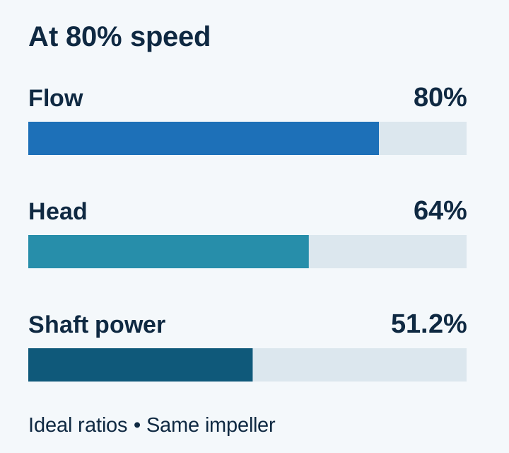
Ideal centrifugal ratios at an assumed speed ratio of 0.8. The chart explains the relationship; actual service and electrical losses need separate checks.
Hypothetical calculation: assume a suitable centrifugal load requires 15 kW shaft power at full speed, with constant motor efficiency 0.90 and drive efficiency 0.97. At r = 0.8: P_shaft = 15 × 0.8³ = 7.68 kW; P_input = 7.68 ÷ (0.90 × 0.97) = 8.80 kW. This point must still meet the equipment's required service.
For a same-period illustration, assume the old fixed-speed system uses 15 ÷ 0.90 = 16.67 kW during all 4,000 annual operating hours, including throttled operation. Assume the new system can serve the same demand at r = 0.8 for 3,000 hours and full speed for 1,000 hours. Holding efficiencies constant for this example:
| Equal 4,000-hour comparison | Explicit calculation | Annual electrical energy |
|---|---|---|
| Assumed fixed-speed baseline | (15 ÷ 0.90) × 4,000 | 66,667 kWh |
| Variable-speed option | [7.68 ÷ (0.90 × 0.97)] × 3,000 + [15 ÷ (0.90 × 0.97)] × 1,000 | 43,574 kWh |
| Difference under these assumptions | 66,667 − 43,574 | 23,093 kWh |
Swipe or scroll horizontally to see every column.
Annual energy = Σ(P_input,i × h_i). Rebuild both columns from the site's actual duty profile, measured baseline and equipment curves before using the difference in a budget. In particular, a throttled fixed-speed fan or pump may draw less power than the assumed constant baseline.
The same-period ownership comparison is TCO = installed package + commissioning/integration + energy + maintenance + downtime over the chosen evaluation period. Include the bypass assembly, sensor work, BMS point mapping, acceptance testing and spare-drive strategy in both quotes. Calculate annual energy cost as kWh × the site's tariff; no tariff or equipment price is assumed here. A lower drive price can be offset by omitted controls work or additional downtime. Assess power-quality equipment where the supply, EMC environment or motor-cable assessment identifies a need.
What must BACnet or Modbus integration actually deliver?
Ask for the exact network variant and a tested point list. BACnet MS/TP and BACnet/IP use different network arrangements; Modbus RTU and Modbus TCP also require the correct interface. A protocol family name on a quotation does not confirm the port, option card, firmware or usable data points.
BACnet's public standard overview describes the exchange of commands, data and status for building automation, under EN ISO 16484-5. The overview does not establish any particular drive's conformity or project approval. Request the candidate's current protocol documentation and, where specified, its PICS and applicable BTL listing. For Modbus, request the register map, data types, scaling and supported read/write functions.
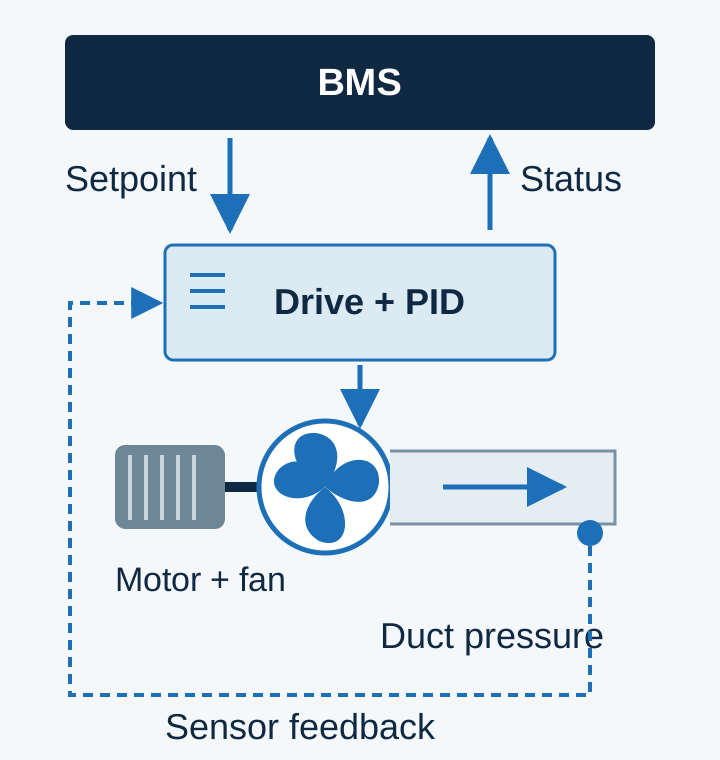
One possible allocation: the drive runs the local pressure loop while the BMS supervises setpoint and status. If the BMS owns PID instead, document that allocation and test its fallback.
| Handover item | Agree in the point schedule | Acceptance evidence |
|---|---|---|
| Enable and speed/setpoint | Writer, units, limits, local/remote priority | Commanded and actual state agree in each permitted mode |
| Pressure or temperature feedback | Sensor source, scaling, fault action; one assigned PID owner | Compare the displayed value with a reference and check response under the approved test procedure |
| Run, fault and availability | Separate command from actual running, trip and bypass status | Simulated states reach the BMS with the agreed descriptions |
| Network or sensor loss | Agreed timeout, alarm, stop/hold/fallback behavior and restart authority | Controls contractor records the approved loss-and-recovery test |
Swipe or scroll horizontally to see every column.
A local drive PID can regulate a process while the BMS supervises it, but this is a selection option to verify. Avoid two controllers correcting the same pressure loop without an intentionally designed hierarchy.
Is fire override the same as an electrical bypass?
Specify them separately. An emergency override changes the control sequence or priority; an electrical line bypass provides a separate motor power path around the drive. A feature name establishes neither a compliant smoke-control system nor the required emergency behavior.
| Requirement | What to establish | Dominant Failure Mode & Prevention |
|---|---|---|
| Emergency or smoke-control override | Project-approved cause-and-effect, command source, operating mode, retained protections and reset authority | A normal control or trip response conflicts with the approved emergency sequence; have the responsible designer and commissioning team verify the exact product behavior |
| Line bypass for continuity | Suitability for line-speed operation, motor protection, interlocking, transfer method and permissives in bypass | Motor operation bypasses a needed process permissive or the two power paths conflict; require the panel's documented design and approved functional tests |
| Local manual operation | Which commands and permissives remain active in hand mode | Hand operation defeats a required damper/flow condition; verify the mode matrix during handover |
Swipe or scroll horizontally to see every column.
An official bypass-control application note reviewed for this page demonstrates that damper feedback can be handled within a particular bypass package. Do not assume the same logic in another panel. The project designer must define which interlocks remain active in normal, manual, bypass and emergency modes. This selection page provides no terminal wiring or fire-system settings. Discuss the documented assembly scope through the VFD panel category.
What should the commissioning handover contain?
Require records against the agreed sequence rather than a screenshot showing that the motor turns. Ask the responsible installer and controls contractor to record:
- The supplied drive/panel code, motor data, selected duty rating and documented site derating.
- Proven fan rotation or pump flow, permitted speed range, and service at the minimum approved demand.
- Local/remote control ownership, point scaling, alarms and the agreed sensor/network-loss recovery.
- Applicable damper or flow permissives in each operating mode, plus the approved bypass/emergency test records where included.
- The final parameter backup, BMS point schedule, equipment documents and a clear list of unresolved exceptions.
For HVAC, the useful handover record pairs each commanded mode with the airflow or water-flow condition it must preserve.
What to send us for an HVAC drive enquiry
Send the inputs that affect selection and quotation scope. Mark an unknown field as unknown so the sourcing discussion can identify the missing document.
| Item | Why we need it | Example format |
|---|---|---|
| Motor and supply data | Match motor type, voltage and required current | Transcribed nameplate fields and supply phase/voltage |
| Application and limits | Define AHU, tower or chilled-water duty and permitted operation | Equipment identifier, curve, minimum flow/airflow and permitted speed range |
| Site and cable conditions | Check enclosure, rating conditions and accessory scope | Location temperature/altitude, cable type and length |
| BMS integration | Identify interface, option and controls responsibility | Protocol variant and point schedule with units/fallback |
| Bypass/emergency requirement | Separate power-path and sequence requirements | Designer-approved mode matrix and assembly scope |
Swipe or scroll horizontally to see every column.
Method, sources and review date
This page combines official energy guidance, public protocol scope and manufacturer application documentation into a buyer selection record. The worked energy values are explicitly hypothetical, not product ratings or an installed-project result. Sources reviewed 19 October 2026:
- U.S. Department of Energy, Adjustable Speed Pumping Applications, Tip Sheet 11 (January 2007): affinity relationships and static-head boundary.
- Natural Resources Canada, Variable Frequency Drives: fan/pump control methods and real-system effects.
- BACnet Committee, About the BACnet Standard: communications scope, EN ISO 16484-5 and the distinction between a standard and product certification.
- ISA, Micro VFDs Gain Macro Features (May 2022): local PID and networking context. ABB Technical Note 242 Rev A (effective December 2025): a product-specific example of damper control in drive and bypass modes; its settings are not generalized here.
First publication and latest substantive revision: 19 October 2026.